Continue to Site

Welcome to our site!

Electro Tech is an online community (with over 170,000 members) who enjoy talking about and building electronic circuits, projects and gadgets. To participate you need to register. Registration is free. Click here to register now.

  • Welcome to our site! Electro Tech is an online community (with over 170,000 members) who enjoy talking about and building electronic circuits, projects and gadgets. To participate you need to register. Registration is free. Click here to register now.

another FM transmitter project

Status
Not open for further replies.
Did you mean that your sinewave has 2 peaks- Positive 5.1V and Negative -4.4V? So due to this two peak voltages you multiplied 1.414 x 2? But all AC has negative and positive peaks......um....
Can you say in basic please!
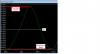
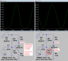
Look at my simulation where it shows a positive peak of +5.1V and a negative peak of -4.4V. They are different due to distortion. Their total is 9.5V.
Each of the two peaks has an RMS voltage that is the peak divided by 1.414 so both have an average RMS voltage that is the total divided by 2.828.
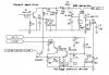
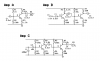
 

Attachments

  • peak voltages.png
    peak voltages.png
    27 KB · Views: 268
No 16dB is 40 times.

The formula is _dB = 10 log (p1/p2)

where p1 and p2 = power 1 and power 2 respectively.
For example if p1 = 5mW and p2 = 10mW
5/10 = 0.5
LOG(0.5) = 0.3
10 x 0.3 = 3dB (gain)

if we reverse the values.
10/5 = 2
LOG(2) = -0.3
10 x 0.3 = -3dB (loss)

To convert dB back to gain.
16db / 10 = 1.6
10^(1.6) = 39.8 (close enough to 40 times)

These examples are for power.
If voltage (or current) is used, then the formula is dBV = 20 log (v1/v2)

But I also found little unusual-

I got LOG(0.5) = -0.3 instead of "LOG(0.5) = 0.3".

And I got LOG(2) = 0.3 instead of
"LOG(2) = -0.3"

just opposit of Trash. Am i wrong?
 
Many years ago in school I used my slide rule to calculate logarithms. But in my career I NEVER used LOGs.

I simply learned the basics.
6dB is double of half the voltage. 3dB is double or half the power. Simple stuff.
 
Hi, here is a circuit which protects the output transistor from accidental SWR. If SWR increased, the supply to the output transistor (via Q2) will decreased, wow!

- I am little confused on C12 (polarized). I think on original circuit, there is only "1" so I guessed 1uF. Or should I have to show you a original old circuit?

- And I think I can use almost any transistor as Q2 which has Ic= 2A or 3A (like BD135?). And any general PNP and NPN as Q3, Q4, Q5 like BC557 (PNP) and BC547 (NPN). Any huge mistake?

-And....it's designed to almost 25 or 30 watt Tx. The rectified voltage is through 10k potentiometer so I thought it can work even at 1 watt Tx or even at 100watt Tx, isn't it?
 

Attachments

  • Auto SWR protection.PNG
    Auto SWR protection.PNG
    9.2 KB · Views: 314
Last edited:
Many 27MHz transmitters for old radio controlled toys blew up if the SWR was bad (when the long antenna was not extended).
I have never seen a protection circuit that you found.
 
OK will post as new thread
 
Many 27MHz transmitters for old radio controlled toys blew up if the SWR was bad (when the long antenna was not extended).
I have never seen a protection circuit that you found.

small tx (mod 4) won't burn its last transistor without antenna. Can you guess how much power can burn the output transistor like 100mW or 500mW or 1 watt or 5 watt or more?
 
The last transistor in my mod 4 FM transmitter has a fairly high output impedance from the tuned LC collector load and it forms a poor match to the 75 ohm antenna so if the antenna is disconnected the power (heating) in the transistor will increase only slightly.

If the impedances are matched when the antenna is disconnected then I think the heating in the last transistor would double.
 
I found these different audio pre amps on professional Cassette player amplifier. All transistors are BC549. May be voltage is +12 (I didn't see the circuit's supply), there is a 12-0-12 Volt output transformer so. I found the polarity of polarized capacitor has been ignored.

There are very diffferent amp bias on same transistor, for why? May be for different gain.
This type of VERY different rang of bias is possible due to large range of hFE of BC549 or what? Can we do with 2N3904?
 

Attachments

  • diff amps.png
    diff amps.png
    8 KB · Views: 280
A 12V transformer produces a rectified and filtered 16V supply.

The Amp A circuit has the transistor biased wrong for a 16V supply. It is almost saturated. I changed R2 to 91k and it works.
Maybe the original circuit used a +6V supply.

The Amp B circuit has the first transistor with no bias voltage so it will not work.

The Amp C circuit has the two transistors biased differently and I do not know why.
 

Attachments

  • transistor.png
    transistor.png
    37 KB · Views: 251
A 12V transformer is 12VAC RMS. Its peak voltage is 1.414 times higher at 17V.
The rectifier drops about 1V and the main filter capacitor will be at about +16V.
 
When I biased Mod 4's preamp using 150K and 27K voltage devider, its starts to distort (too high amplify) so I used 47K for mic bias and only 47 on attanuator. Even got little (but fine) distortion if I talked near of mic (near from half meter). Is it ok as your calculation?
[Don't be confuse on schematic: I used the attnuator and the mic separately, not together like on the attached schematic. While using attenuator I removed 47K and Mic. While using Mic I removed attenuator network (123 resistors)]
 

Attachments

  • 150k vs 27k attnuator.png
    150k vs 27k attnuator.png
    3 KB · Views: 263
Last edited:
Your mic preamp does not have a supply voltage. It MUST be +5.0V.
The mic will distort at high sound levels when its current is too low. 47k to bias it is too high a resistor value.

10mV RMS is a loud signal from an electret mic. I simulated the circuit with an input that is 50mV RMS and it shows normal single transistor distortion when the level is this high:
 

Attachments

  • FM mic preamp.png
    FM mic preamp.png
    30.7 KB · Views: 258
But I used 10k mic resistor and got more high level distortion and used 22k but also got distortion, and used 33k but also got little distortion, and lastly use 47k, then got very little distortion. :) so guessed if I used 56K, may be distortion would be zero :)
 
And now I completed by making Mod-4. Layout design was attached before few page designed with ExpressPCB. I got success without any mistake and now transmitting at 93.6 MHz. There is no difference between listening song directly from MP3 player and listening same song through the FM transmitter. Quality is 98% if MP3 has 100%! Wow! Almost no one can differ this 2%.
So quality of this Tx amazed me again! As a whole there is no difference between MP3 player and FM transmitter in quality (rest of stereo). It has really empty carrier noise! Wow!

I added a power indicator LED, look at picture. How might be the average current consumption of the LED at 5V with 680 ohms resistor?
 

Attachments

  • My Mod-4.jpg
    My Mod-4.jpg
    46.8 KB · Views: 258
Your pcb is nice and compact.
I notice a huge 1A regulator instead of a little 100mA one.

The current in an LED is determined by Ohms Law, the supply voltage and the resistor value.
A red LED is 1.8V to 2.0V. With a 9V supply, the 680 ohm resistor has 7.1V across it so its (and the LED's) current is 7V/680 ohms= 10.4mA. The current drops as the battery voltage runs down.

My Mod-4 transmitter also has a 680 ohm resistor for limiting the current to a red LED but I never connected an LED.
 
I notice a huge 1A regulator instead of a little 100mA one...

A red LED is 1.8V to 2.0V. With a 9V supply...

sorry I cannot find any low dropout 100mA small regulator, so.

I used 5V supply for LED through 680R. So current consumption might be low.
 
sorry I cannot find any low dropout 100mA small regulator.
ALL American and European semiconductor manufacturers make many small low dropout voltage regulators. The regulator I use is made by National Semi (Texas Instruments now), ON Semi and ST Micro. Digikey is the largest distributor in North America and they have more than 12,000 in stock plus many that are surface mount. Farnell is worldwide and also has many in stock.
Linear Technology also make many low dropout regulators and the distributors stock thousands of them.

I used 5V supply for LED through 680R. So current consumption might be low.
Then the regulator heats up instead of the resistor and the LED might be so dim that it might not be visible in daylight.
When the 680 ohm resistor connects directly to the 9V battery then the LED has 11mA when the battery is new and the current and brightness drop as the battery voltage runs down so you can see that the voltage is getting low.
 
ALL American and European semiconductor manufacturers make many small low dropout voltage regulators.

It is not available on my area and most important shops of city. I tried for online shoping from China where all components are very cheap. But price of LM2931 was almost 0.90 USD per piece. And shipping charge was almost 45 USD! So it was not affordable.

Here is a small problem!
I want to connect my cell phone's audio and Mic to PC using earphone of cell phone (earphone has 2 small speakers and an electret Mic). First, I connected directly 'audio out' (cell phone) to 'Mic in' (PC) and Line out to Mic, but it was noisy. I think I feed high level audio to low level Mic so it was distortion, isn't it? So I need attenuator.

- I used 1st attenuator to attenuate the audio signal of cell phone's Audio (R Gnd) to feed the Mic in of PC. Hoping that audio level on earphone speaker will not be attenuated (?). Resistors' values are just guessed :)

- I am confused on 2nd attenuator because I have to attenuate ONLY the signal of 'Line out' of PC to feed the 'Mic in' of cell phone. But If I simply added an attenuator then the attenuator ALSO attenuates the signal of electret Mic of earphone and it is not good I think. Then how to add attenuator here?

Help me including all approx values of resistors please!
 

Attachments

  • Pradeep.png
    Pradeep.png
    5.2 KB · Views: 250
Last edited:
Status
Not open for further replies.

Latest threads

Back
Top