Continue to Site

Welcome to our site!

Electro Tech is an online community (with over 170,000 members) who enjoy talking about and building electronic circuits, projects and gadgets. To participate you need to register. Registration is free. Click here to register now.

  • Welcome to our site! Electro Tech is an online community (with over 170,000 members) who enjoy talking about and building electronic circuits, projects and gadgets. To participate you need to register. Registration is free. Click here to register now.

another FM transmitter project

Status
Not open for further replies.
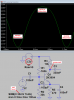
If i added a little series inductor on Mod 4 (2/3 turns) at its RF output before capacitor (LC>inductor>capacitor>Ant), hope i will able to get little low output impedance, little suitable for whipe antenna. Can't I?

I am designing a PCB layout of mod 4 and want to add a small PCB etched inductor. :)
 
Last edited:
The inductor and capacitor must have the correct values so the LC does not attenuate the signal.
 
In Mod 4, I think all VHF transistor will work in oscillator and in last amplifier with very good performance. But I think 1st amp biasing is critical for transistor change. You biased for 2n3904, will this biasing work in 2n4401? May be voltage devider is critical here. If it is easy, may I see a pre-amp biasing using 2n4401?
 
The 2N3904 preamp transistor operates at about 0.3mA in my FM transmitter audio preamp.

The datasheets show that the minimum hFE of a 2N4401 is half the hFE of a 2N3904 at 0.3mA. Then the 2N4401 will be almost cutoff and will cause severe distortion. But the average hFE are almost the same so some 2N4401 transistors will work fine. It works fine in a simulation.

Measure the DC voltage at the collector and change the value of the 160k bias resistor so that the voltage is from 2V to 3V.
 

Attachments

  • 2N3904 vs 2N4401.png
    2N3904 vs 2N4401.png
    19.8 KB · Views: 232
Woooo...............!!! I learnt simulation!!!!!!! I used to be failed while running the schematic, today I wrote your simulation command on simulation command box like this- ".trans 0 4050 4000 50p" Hahahahaha I got success! How easy it is, laughing at my sillyness :p

I changed the both coupling capacitor with 300pf and got higher output. There is 5.1V to -5.1V peak to peak voltage, wow! It shows the higher output of the transmitter, isn't it?
 

Attachments

  • Simulation.png
    Simulation.png
    28 KB · Views: 231
I am glad to see that you have LTspice IV working.
You can tweak capacitor values to get lower harmonics and a higher output like this:
 

Attachments

  • FM transmitter 4.png
    FM transmitter 4.png
    26.8 KB · Views: 260
I am glad to see that you have LTspice IV working.
You can tweak capacitor values to get lower harmonics and a higher output like this:

I thought I did the best of 5.1V peak to peak, but amazing you got 6.5V peak wow!

But still cannot simulate the Pre-amp. You attached a simulation image at 32 page of this thread, but the image has been disabled (removed?) :( So I cannot get hints to simulate.

May I see the pre-amp simulation image once again please!

(And also- I placed 2n4401 and used 140K and 27K base bias resistor in pre-amp. Then I got 2.1V at its collector. Hope this biasing will work as a pre-amp without cut-off or saturation)
160k/30k is a ratio of 5.333 and 150k/27k is a ratio almost the same of 5.556.
Here is the comparison of the two which have very little difference:
 

Attachments

  • FM tx mic preamp biasing.png
    FM tx mic preamp biasing.png
    36.9 KB · Views: 246
160k/30k is a ratio of 5.333 and 150k/27k is a ratio almost the same of 5.556.
Here is the comparison of the two which have very little difference:

if it is related to "Ratio" then I think I can use 16K and 3K :) . OK I will simulate! Thank you!
 
If you use 16k and 3k then the input impedance is so low that a HUGE input coupling capacitor is needed from the mic and the signal level from the mic will be attenuated.
It causes the transistor output to be clipped on the bottom because the divider current is much higher than the base current so the divider voltage is higher than if the resistors had higher values.
 
How amazing electronics!!
Ya I simulated and got clipped on the bottom of output waveform. But when I used 6.8K and 3K bias resistors, the collector wave is very fine. But it has 314mV to 389mV peak to peak only. How to say it is bad?
 
Ya I simulated and got clipped on the bottom of output waveform. But when I used 6.8K and 3K bias resistors, the collector wave is very fine. But it has 314mV to 389mV peak to peak only. How to say it is bad?
The ratio of the bias resistors is wrong so that the transistor is almost saturated which causes the gain to be too low. Try using 1.2k instead of 3k.

With resistor values much too low then the input coupling capacitor C1 value must be much larger so it is not a highpass filter cutting most low and medium frequencies.
 
- Here on 2nd page I found a simple "Ferrite slug transformer" to match the impedance between Tx and Ant. May be it will work, won't it?

-Here on 3rd page he is saying about your transmitter. He is saying 'since it is buffer, output coupling 22pf is not needed, it reduces the transmission range'. Actually is it? I think 22pf separates LC with antenna and reduces overload (or external capacitance) to LC and keeps smooth gain. And also it matches impedance little (am I right?)
- Also he is saying "It consumes more than double current unnecessarily". What he is saying?
 
talkingelectronics..... Here on 2nd page I found a simple "Ferrite slug transformer" to match the impedance between Tx and Ant. May be it will work, won't it?
No.
The high impedance collector of the RF transistor should have a pi filter (a C to ground, a series L and another C to ground) then connect the low impedance antenna.

Here on 3rd page he is saying about your transmitter. He is saying 'since it is buffer, output coupling 22pf is not needed, it reduces the transmission range'. Actually is it? I think 22pf separates LC with antenna and reduces overload (or external capacitance) to LC and keeps smooth gain. And also it matches impedance little (am I right?)
- Also he is saying "It consumes more than double current unnecessarily". What he is saying?
Hee, hee, hee. I did not know that Collin criticized my FM transmitter.
I disagree with many things he said. My range is more than 2km and it sounds much better than his muffled transmitters (he is deaf and wears a hearing aid)!

On a simulation, the output level is reduced and the harmonics are increased when the output coupling capacitor value is increased so it is like a piece of wire:
 

Attachments

  • FM transmitter output coupling cap.png
    FM transmitter output coupling cap.png
    28.5 KB · Views: 232
I tested the collector of oscillator and saw the waveform, Shocked!
How many harmonics are there! But it is fine after buffer. If I made a FM Tx just including oscillator, will this happens? How bad output it is!
 
If I made a FM Tx just including oscillator, will this happens? How bad output it is!
In my simulation the oscillator stops when the 75 ohm antenna is coupled to the collector with a capacitor value greater than 6.8pf. The output is distorted (the bottom of the waveform is clipped).
When the 75 ohm antenna is capacitor coupled to the emitter then the waveform is extremely distorted with an amplitude of only 1.8V p-p.
 
I found low drop-out regulator but is 3.3V only (78L33). If I used it instead of your regulator, are there any huge difference on operation or on output?
 
An L78L33 is not a low-dropout regulator. It is just an ordinary little 3.3V regulator. My FM transmitter uses a very common little 5V low-dropout regulator.
EVERY modern semiconductor manufacturer makes a few 5V low-dropout regulators.

If you use the 3.3V regulator:
1) The preamp will not work properly unless its biasing is changed and its maximum output level might be too low.
2) The oscillator output will be low which will make the range not far.

Here is a simulation of the preamp transistor:
 

Attachments

  • FM preamp.png
    FM preamp.png
    23.3 KB · Views: 232
At 5V, you wrote 80mV SINE but at 3.3V you wrote 30mV, how you calculated? Automatically via LTspice or manually?
 
At 5V, you wrote 80mV SINE but at 3.3V you wrote 30mV, how you calculated? Automatically via LTspice or manually?
80mV peak (not SINE) is a loud sound. Then the preamp with a 5V supply performs very well.
But with the 3.3V supply the output of the preamp is horribly distorted. So I reduced the input to only 30mV peak that is not loud then the output is better but is still distorted pretty bad.
 
Status
Not open for further replies.

Latest threads

New Articles From Microcontroller Tips

Back
Top