Continue to Site

Welcome to our site!

Electro Tech is an online community (with over 170,000 members) who enjoy talking about and building electronic circuits, projects and gadgets. To participate you need to register. Registration is free. Click here to register now.

  • Welcome to our site! Electro Tech is an online community (with over 170,000 members) who enjoy talking about and building electronic circuits, projects and gadgets. To participate you need to register. Registration is free. Click here to register now.

Bluetooth integrated FM transmitter project

devil777

New Member
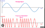
For semester project, I am planning to choose this topic. The audio is first received using the bluetooth module, do the necessary processing and transmit that signal through certain frequency using frequency modulation.
The main thing is that I want to do it but don't know how to do it.
Is it possible to do it? And how?
What materials will be required at exact?
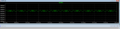
Can you guys please send the simulation file for either proteus or for LTspice for transmitter showing the frequency modulation clearly?
Helpp meeee!!
 
Firstly, re. homework help, you are expected to do at least an initial the design then ask about possible problems; not get others to do the work for you.


For the bluetooth side, a BM62 module is probably a reasonable approach. Bluetooth requires complex, custom integrated circuits so a module with accessible terminals is likely the only possibility. There are many other module types, but a lot of the cheaper ones are data only or clones with very variable reliability and specifications.


FM is quite simple, you add a varactor (varicap) diode to the oscillator; or feed low level audio in to the VCO control on a synthesised transmitter.

Or you can use phase modulation, applied to the signal after the oscillator. With suitable audio preemphasis that produces exactly the same FM output signal.

Re. the transmitter side:
Note that transmitting audio without a very specific licence is illegal pretty much worldwide.

So is using home-made transmitters; every transmitter type must be certified to not cause interference or use excess power.

You can use extreme low power, a microwatt or so, basically oscillator leakage without any antenna, but that's about the limit of it.

(Commercially made RF modules for such as bluetooth,wifi and other specific defined systems from major manufacturers, are pre-certified to conform to frequency and power regulations).


Having said that - here are a couple of example ham radio transmitter FM VHF designs, that will show some of the concepts involved.
(I noticed a typo on this one - the last paragraph of the section about the phase modulator should say "The audio signal is given to the TR3 gate" - it should TR4 gate).


Amateur [ham] radio training and technical resources are a gold mine when you want to learn about radio design or RF in general; there are frequency bands dedicated for amateur use slotted in throughout the RF spectrum, from 1.8 MHz all the way up to the terahertz region.
(You still need an appropriate level of licence to transmit on any, and a higher level of licence to build and certify your own transmitting equipment, rather than using commercially built gear).
 
Unlicensed FM in US :

Part 15 Devices​

Unlicensed operation on the AM and FM radio broadcast bands is permitted for some extremely low powered devices covered under Part 15 of the FCC's rules.

Has the following restriction:

Although an operator does not have to obtain a license to use a Part 15 transmitter, the transmitter itself is required to have an FCC authorization before it can be legally marketed in the United States.

So pre-certified type gear as I mentioned, not home-built equipment.
 
Yes, for "legally marketed", OP can comment on that, if thats an intention
for project. Otherwise OP does not need a license. Which I think we are stating,
with clarification.

Regards, Dana.
 
Yes, for "legally marketed", OP can comment on that, if thats an intention
????
It's the Part 15 classification (roughly equivalent to "type approval" of licence exempt devices in the UK) by the manufacturer that allows the use by unlicensed individuals.

Any non-exempt transmitter, such as home made, requires the operator to be licenced and competent to certify the device for such as spurious emissions and power limits etc.

There is no get-out where a home built transmitter is legal to use, unless it's microwatt leakage level (no antenna) or it's built by someone with an appropriate class of licence.
 
OK, not quite the same as the UK - see page 3 of this document, covering home-built equipment:

It is permitted to built devices that would comply with Part 15 regulation, as long as you have the facilities to ensure the power and bandwidth limits are obeyed.

For the 88-108MHz broadcast FM band, the limit is 250uV per metre at 3m from the antenna.

That is approximately 11 nanowatts in to a half wave dipole.
Hey thanks for the help sir... i initialized my work few weeks ago but I am unable to get the frequency modulated signal in the output. It gives AM signal. I tried in both proteus and in LTSpice. Can you show me where am I wring please? I have already tried a lot of circuits I found, like from audio guru and many others.
 

Attachments

  • received_302660892208107.jpeg
    received_302660892208107.jpeg
    64.3 KB · Views: 109
  • received_2449984905185075.jpeg
    received_2449984905185075.jpeg
    164.6 KB · Views: 89
  • received_1740541239766780.png
    received_1740541239766780.png
    44.5 KB · Views: 88
Hey thanks for the help sir... i initialized my work few weeks ago but I am unable to get the frequency modulated signal in the output. It gives AM signal. I tried in both proteus and in LTSpice. Can you show me where am I wring please? I have already tried a lot of circuits I found, like from audio guru and many others.

It's not a 'real' transmitter, it's just a toy - it gives both AM and FM modulation at the same time.
 
As Nigel says, that is not a good FM design.

The simplest improvement is probably to add a varicap diode. A 1N4007 usually works pretty well!

1N4007_Capacitance.png


For your circuit, try this: Disconnect the right hand side of C2 to start with. Connect the diode cathode to V+ and its anode to the collector with a small cap, eg. 47pF should be reasonable, at a guess.

Add two, 1M resistors in series across the supply and connect the junction of those to the diode anode, to reverse bias it at around half supply.

Then connect either an RF choke 10K resistor to the right side of C2 and also connect that to the diode anode.

You will have to re-tune the circuit. Hopefully that should then give a better FM signal??

You may have to try different diodes, as the varicap effect is usually good but not consistent from one to the next.

I'd also suggest adding a ceramic cap such as 0.1uF across the power, rather that rely on the battery passing all the high frequencies.
 
Hello sirs. I tried a lot of circuits but I didn't get tha waveform like this in any software(Proteus or LTSpice). I have to show the simulation at first as demo in presentation. Is this simulators errors or am I doing wrong somewhere? Iam unable to get frequency modulated waves. My friends also demotivate me saying "If I can't even show correctly in simulation, How can I make the real thing" help me sirs. Show me the way.
 

Attachments

  • Screenshot 2023-12-13 170940.png
    Screenshot 2023-12-13 170940.png
    57.4 KB · Views: 85
Post your simulation file.

Basically your sim should be a transient sweep with a Varicap freq
source close to the freq of the main FM oscillator, so you can see the
variation in modulated waveform.


Regards, Dana.
 
Last edited:
I dont know which one to post since I tried a lot of ones. But this is the basic one. I put the values of capacitor and inductor in LC oscillator part in such a way that it resonates in this simulation using that formula I read. The blank wire is for antenna.
 

Attachments

  • trans.asc
    2.7 KB · Views: 85
You have to set your timestep and len of sim correctly :

1702475019396.png


To get a more stable pic I should have started data collection even later to allow
osc to start up fully.

Notice your modulating freq is actually high to produce this :

1702476459771.png


Regards, Dana.
 
Last edited:
I tried a lot of circuits but I didn't get tha waveform like this in any software(Proteus or LTSpice).
It is unlikely that you will be able to actually produce a waveform like the one you show in post #12.
The frequency of the modulated wave is changing by a factor of about 2:1 during the modulation cycle.

A simple FM modulator does not change the carrier frequency anything like as much as shown in that textbook diagram.

You are trying to make a 100MHz transmitter which in a practical system would have a frequency deviation of 75kHz.
That is a frequency change of 0.075/100 that is a 0.00075:1 ratio.
You will barely see that on a 'scope trace.

My friends also demotivate me saying "If I can't even show correctly in simulation, How can I make the real thing"
Have all these comedians who you call "friends" managed to do it?
I suspect that they have not.

JimB
 
I changed the position of ground connection, took antenna from the upper blank wire and got similar result as that of Frequency Modulated wave but I don't think it will practically work does it?
 

Attachments

  • received_964462251913620.png
    received_964462251913620.png
    7.4 KB · Views: 87
  • received_24448704381410704.png
    received_24448704381410704.png
    21.3 KB · Views: 89
Also the circuit you have does not modulate the reactive impedance of the
tank network, seems to look more like a AM mod circuit.

Here is a circuit where a varactor is used :

1702477668292.png


Here D2 changes its C with applied modulating V, which is reflected across tank to
change its resonant freq.

Regards,. Dana.
 
Have all these comedians who you call "friends" managed to do it?
I suspect that they have not.

JimB
Sir, its the project that I chose for myself to do it so I guess the only help I am going to get is from this group. Thank you everyonee sirs. I am really grateful and happy being helped.
 
Your capacitance of 10nF for your C3 is 21 times higher than is needed and it cuts high audio frequencIes like an old AM radio or old telephone.
All FM radios have de-emphasis (treble reduction) then all FM transmitters have complementary pre-emphasis for good sounds. Your simple circuit is missing pre-emphasis so a receiving radio will sound VERY muffled.
 

Latest threads

New Articles From Microcontroller Tips

Back
Top