Electro Tech is an online community (with over 170,000 members) who enjoy talking about and building electronic circuits, projects and gadgets. To participate you need to register. Registration is free. Click here to register now.
Welcome to our site! Electro Tech is an online community (with over 170,000 members) who enjoy talking about and building electronic circuits, projects and gadgets. To participate you need to register. Registration is free. Click here to register now.
I don't know why FM station frequencies are not managed properly in your country.
Here, car radios and home stereos have digital tuning. Since our FM frequencies are only odd (89.9MHz, 90.1MHz, 90.3MHz, 90.5MHz etc) then the digital tuning only tunes to an odd frequency so the 90.0MHz crystal transmitter will not work. Fm transmitters whose frequency drifts also will not work.
Thanks, but I do not always have patience. A few people here like Willen I have chatted with for many years.
I usually help polite students who show that they like electronics. Some students do not know what they want to become and they picked "an electronics career" out of a hat without even liking electronics. I tell them to do gardening instead.
I assisted one student in the Philippines do his final year project and he graduated from university then got a good job. He chatted from an internet cafe.
Really i felt too!
I like to post every thread here because the answer from audioguru is reliable!! .ON some thread, I felt he can't be "patienced" on learners ' sillyness. I felt on my few silly questions
I don't know why FM station frequencies are not managed properly in your country.
Here, car radios and home stereos have digital tuning. Since our FM frequencies are only odd (89.9MHz, 90.1MHz, 90.3MHz, 90.5MHz etc) then the digital tuning only tunes to an odd frequency so the 90.0MHz crystal transmitter will not work. Fm transmitters whose frequency drifts also will not work.
I thought- if there are lot and lots of stations, there should be a Digital tuning system for accuracy. But in my country, here are no more stations and more frequencies are empty. So I think it is not managed and i think here are using LC tuning radios. When we will have lot and lot FM statios like in Canada, then we will going to fall in problem of managing frequencies i think.
-There are almost same LC tuning system on Basic Tx and Rx. If I removed few turns from 'L' of Tx, I can get 109 or 110 MHz (or higher). If I also removed few turns from 'L' Rx, does this Rx able to receive (demodulate) this 109 or 110 MHz? And same thing can i do with 94 or 95 MHz (Or lower) by adding few turns on both 'L' of LC?
Be careful with the frequency of your transmitter. The worldwide aircraft communications radio band is immediately above the FM broadcast band from 108MHz to 137MHz. Do not cause interference.
The old and simple transmitter that uses a 10MHz crystal operates on only 90.0MHz.
A modern crystal FM transmitter uses a frequency sythesizer that can operate on many frequencies.
Once, you have said that- This kind of biasing is very bad way. Talking about last RF amplifier stage which has 330R at the collector. May be you also said- It will not amplify well (I think). OK, then I am thinking about to remove the 330R and add an inductor. Hope this modify is little better than resistor, isn't it?
Can I calculate the Base voltage (voltage devider) of preamp of Mod 4 like this way?
Base current = 5V / (160K+30K)= 0.026mA
Then Base Voltage= (0.026mA x 160k)= 4.16 V
(any mistake?)
Then emitter voltage should be arround 3V i think, and it is possible from 470R. But getting confuse how to calculate the Emitter voltage (and collector voltage too)?
No.
THE DIVIDER's current is 26.32uA.
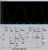
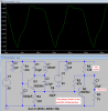
The SIM shows that the collector is at 2.0V so the collector current is (5V - 2V)/10k= 0.3mA.
The hFE of the 2N3904 at 0.3mA collector current is about 260 so its BASE CURRENT is 300uA/260=1.15uA.
Then the 160k resistor has a current of 26.32uA + 1.15uA= 27.47uA and the 30k resistor has a current of 26.32uA - 1.15uA= 25.17uA.
The base voltage IS NOT the voltage across the 160k resistor, it is the voltage across only the 30k resistor which is (25.17uA x 30k=) 0.755V.
My simulation shows a base voltage of 0.7646V which is within 1% of my calculated voltage.
Hi Ag, i still use my s8050 almost one year now it runs off a mobile phone battery,i don't know it's technical speculations but it works great and clear moreover it's frequency doesn't change automatically unlike the Pn22,bc54v,2n3904 etc
Hi Ag, i still use my s8050 almost one year now it runs off a mobile phone battery,i don't know it's technical speculations but it works great and clear moreover it's frequency doesn't change automatically unlike the Pn22,bc54v,2n3904 etc
The Oriental S8050 transistor does not have a detailed datasheet like a 2N3904 American transistor. Some might work and others might not work in an FM transmitter.
Its capacitance changes when its collector voltage changes (that is how it produces FM) and the capacitance of anything near the antenna changes when distance of nearby objects change. Then of course the frequency changes.
Hi Ag, i still use my s8050 almost one year now it runs off a mobile phone battery,i don't know it's technical speculations but it works great and clear moreover it's frequency doesn't change automatically unlike the Pn22,bc54v,2n3904 etc
Hi will here is the link to my circuit https://ziddique.wordpress.com/2011/12/28/simplest-fm-transmitter/ but you should take AG's advice to account that some s8050s mightn't work but most works..goodluck also there is a micro version of the circuit built with smd components..you can find it on the site
It doesn't have pre-emphasis so the de-emphasis in all FM radios will make it sound awful (no high audio frequencies), especially in North America.
Since FM broadcasting started first in North America we have more pre-emphasis and more de-emphasis than in the rest of the world.
When FM broadcasting began a long time ago the transmitters were not very powerful and the FM radios had poor sensitivity so there was a lot of hiss. The higher amount of pre and de-emphasis reduced the hiss. Now modern transmitters are very powerful and modern FM radios are very sensitive so less pre and de-emphasis works fine but it was not changed in North America.
This site uses cookies to help personalise content, tailor your experience and to keep you logged in if you register.
By continuing to use this site, you are consenting to our use of cookies.

")