Electro Tech is an online community (with over 170,000 members) who enjoy talking about and building electronic circuits, projects and gadgets. To participate you need to register. Registration is free. Click here to register now.
Welcome to our site! Electro Tech is an online community (with over 170,000 members) who enjoy talking about and building electronic circuits, projects and gadgets. To participate you need to register. Registration is free. Click here to register now.
In a wye connected system, it states in my book that if you get the polarity backwards on one of the windings then you reverse the direction of phase rotation. Can someone please give explain.
If you reverse one winding on a Y connected three phase motor it won't work properly. The armature rotates with the magnetic field and with one phase reversed the magnetic field will not rotate at all evenly. In fact, the motor will probably take far more current than it would normally take.
Three-phase motors can be wired Y connected or delta connected. Some can be either, and the terminals of those are arranged so that it is really easy to swap between Y and delta, but really difficult to get the connection of any one winding the wrong way round. That is done because it's important to get the windings the right way round.
This is the usual arrangement.
The connections between W2, U2 and V2, or between W2 and U1, U2 and V1 and V2 and W1 are usually made with solid links, and the terminals are made so that all the distances are the same. Often, if the motor is delivered in a Y - configuration with W2, V2 and U2 connected, only two solid links are needed but three are supplied, to make changing to delta configuration easier.
When a motor is wired in Y or delta, swapping any two of the supply wires will reverse its direction of rotation.
On a single phase induction motor, there are two windings, and usually one has a capacitor in series. On one of those motors you could swap the direction of just one winding to reverse the motor. However single-phase induction motors are not referred to as Y connected.
For BLDC motors, such as those used with >=100W fans, they use Hall sensors, so to reverse any 2 phase of motor drivers and matching Hall sensors must both be swapped.
A BLDC motor only has two windings energized at any one time.
BLDC and AC PM motors reverse all the time without swapping any hall sensor, they just use the relative swapped winding and hall,
I have used them for decades in CNC applications.
if it was 3ph then it was not BLDC, Brushless DC ,BLDC has only two stator windings energized at any one time, As the commutation resembles a DC motor, turned inside-out.
Although the two motors are practically identical, the difference is in the commutation.
High performance BDLC drive systems use field-oriented control, aka vector control, using continuous PWM sine wave drive to each phase, with the drive waveform tracking the rotor angle to maintain 90' between the stator and rotor fields.
It's a similar concept to changing from switching windings to microstepping with stepper motors.
I think the author is saying that when the three phases were originally connected when building the system that one phase connection was installed backwards
In a wye connected system, it states in my book that if you get the polarity backwards on one of the windings then you reverse the direction of phase rotation. Can someone please give explain.
In a 3-phase power system, be it Wye or Delta, there is no such thing as ""getting the polarity backwards on one of the windings". In order to change phase rotation, you always swap any 2 of the leads. This applies to all std 3-phase equipment, be it motor, xfmr, or whatever. In the case of a motor (3-phase induction motor), swapping any 2 line leads reverses shaft rotation. 3-ph reversing starters do just that via two integral contactors, one wired A-B-C, the other wired C-B-A.
Not properly, the same as with a motor in wye (star) connection and a reversed internal winding.
The voltage distribution would be uneven and the star point no longer at near zero volts.
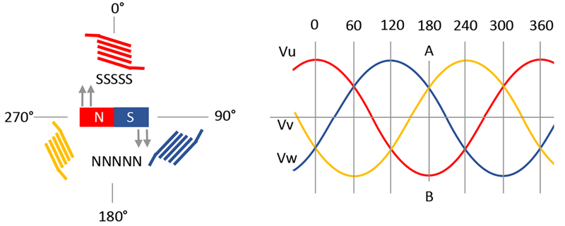
One of the fundamental characteristics of three phase power is that the sum of the voltages is always zero, and in a motor the winding fields sum to zero (allowing for opposite polarities cancelling each other out.
That results in a smoothly rotating north-south (or multiple N-S pairs) magnetic field between the stator poles.
A reversed winding would make the rotation uneven and the motor inefficient, if it did not just overload.
Take a pencil and paper and draw three equal length vectors, label them R,S,T at 0, 120, 240 degrees respectively, and joined at the center.
What you drew is the classical representation of Wye connected three phase system.
Now, invert R, which essentially means adding 180 degrees.
Now draw R, S, T at 180, 120, 240 degrees.
What did you get?
I will allow you now to calculate the vector value of the R to S and R to T. Does this resemble a balanced three phase voltage?
High performance BDLC drive systems use field-oriented control, aka vector control, using continuous PWM sine wave drive to each phase, with the drive waveform tracking the rotor angle to maintain 90' between the stator and rotor fields.
It's a similar concept to changing from switching windings to microstepping with stepper motors.
Not in all the CNC servo's I have been connected with over the decades, if they operate with 3ph they cannot be classified as BLDC , but PM 3ph AC, such as used by Fanuc & Mitsubishi. I have converted some of these with proprietary commutation to BLDC.
The term BLDC comes from Brushless DC, as it simulates a Brushed DC motor turned inside-out IOW, two commutation conductors . Or only any two windings connected at any one time.
This is part of the procedure using a DB 'scope when aligning a BLDC encoder commutation tracks, when back-fed/rotated, the BLDC motor generates 3ph.
This site uses cookies to help personalise content, tailor your experience and to keep you logged in if you register.
By continuing to use this site, you are consenting to our use of cookies.