Continue to Site

Welcome to our site!

Electro Tech is an online community (with over 170,000 members) who enjoy talking about and building electronic circuits, projects and gadgets. To participate you need to register. Registration is free. Click here to register now.

  • Welcome to our site! Electro Tech is an online community (with over 170,000 members) who enjoy talking about and building electronic circuits, projects and gadgets. To participate you need to register. Registration is free. Click here to register now.

Woodworker needs some help.

Status
Not open for further replies.

ksopp

New Member
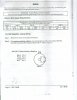
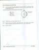
The motor on my circa 1938 drill press finally died. I've replaced it with a new 1/2 hp motor, but am having difficulty wiring the motor for both clockwise and counter clockwise rotation. I have a 6 terminal toggle DPDT switch and the attached diagrams that came with the motor. My goal is to wire this puppy properly without frying either myself or the motor.

I would certainly appreciate the help of someone willing to help someone more familiar with wood than wires.

Thanks
 

Attachments

  • JA06-002.JPG
    JA06-002.JPG
    164.5 KB · Views: 153
  • JA06-003.JPG
    JA06-003.JPG
    85.1 KB · Views: 133
  • JA06-004.JPG
    JA06-004.JPG
    128.3 KB · Views: 129
Hi Ksopp,

Here is one of two possibilities. You can also flip the circuit around
and connect the red and black wires to the two common contacts
and pins 1 and 4 to the no/nc contcts. In other words interchange
red and pin 1 and also black and pin 4.

on1aag.
 

Attachments

  • DPDT switch.GIF
    DPDT switch.GIF
    5.4 KB · Views: 143
Follow up

I attempted to wire as recommended, leaving the internal red and black wires off of a pin. The motor reversed properly given the switch position, but would hum and hesitate before starting. When set up for internal wiring, it starts immediately, but does not reverse.

Any further suggestion would be appreciated.
 
Internal wiring

The first jpeg in the initial post shows a wiring for "internal wiring" where the wires inside of the motor are wired as follows: Black - P4, White -P4, Orange - P1, and Red - Pin1.
 
Hi Ksopp,

You've lost me completely, I haven't got the slighthest idea what
you are talking about. Can you take a few pictures of the motor
connections ?
And another thing, did you reverse the direction while the motor
was running ?

on1aag.
 
My first post included 3 jpegs from the motor manual listing options for wiring:
CCW "internal" wiring, CW "internal wiring, and "External wiring". Using a toggle DPDT switch (on-off-on) I attempted to wired to the schematic shown in eblc1388's post. I did not attach the internal black and red wires inside the motor to a pin. The motor would hum for a second and then start. It would reverse properly when the switch was reversed, though with the hum and delay. When the internal red and black wires were attached to their respective pins, (as shown in the first jpeg) the motor would start immediately, but fail to reverse.

The motor was always allowed to come to a full stop before reversing.

Sorry if my lack of knowledge has confused matters.
 
Hi Ksopp,

Let's try something different.
First remove the switch.
Connect the orange wire to pin 1 and the white wire to pin 4.
Connect the red wire to pin 1 and the black wire to pin 4.
Start the motor and observe the direction of rotation.

Second reverse the red and the black wires, red goes to pin 4
and black goes to pin 1.
Start the motor and observe the direction, it should be the opposite
direction.

on1aag.
 
what do you mean internal wiring ? where the wire came from motor/switch ?

From the original post the internal wiring refers to the connections inside the motor housing for reversing and the external wiring refers to the power cord's three wires coming into the same location.
Since the woodworker wants to be able to reverse the motor then he will require some additional external wiring to his remote switch

The white and orange wires are connected the same regardless of direction,
pins 1 and 4, and the black and red are switched between pins 1 and 4 to reverse the motor.
The red and black need to be connected/extended to the switch as per earlier suggestions and then the wipers of said switch need to be returned to pins 1 and 4.

If it is stalling/ hesitating then the wiring is most likely not tight/good connections, the switch is flaky with a bad internal connection or the switch cannot handle the current load and and its contacts are heating up causing a high resistance.

The full current draw of the motor, either from the start or run windings or both need to be addressed. The switch must have a current rating equal to the motor ratings.

What is the ratings on the switch you are using?
You say the motor is 1/2 hp. What does the motor plate ratings say?
Running hp/current is far inferior to peak/starting current.

cheers

EDIT:Too long typing and didn't see your post or on1aag's.

Do his tests and then respond to my two questions if you like.:)
 
Last edited:
Motor problem

Hi ksopp,

the wiring as already given must work properly. You must not omit connecting the black and red wire to the terminals of the motor. Since the motor is actually a three phase motor (with one artificial phase produced by a capacitor) two phases have to be changed to change the direction.

I've redrawn the wiring for better clarity. If you have a three position switch with a stop position you might omit the 'ON-OFF' switch. It's just drawn to make clear that reversing the direction requires a full stop of the motor before starting reverse.

Don't forget to wire 'PE' (protective earth) properly. Otherwise you might electrocute yourself. :rolleyes:
 
Last edited:
Boncuk said:
Hi ksopp,

Since the motor is actually a three phase motor (with one artificial phase produced by a capacitor) two phases have to be changed to change the direction.

most shop power tool motors are likely a two phase motor, a run winding and start winding with the start winding phase shifted by the cap to provide initial torque. Once sufficient speed is achieved a centrifugal switch disconnects the start winding. It may, however, keep both windings running with the use of a run capacitor. It is still a two phase motor. Run capacitors cost more and are generally used in high load industrial setting.

It's just drawn to make clear that reversing the direction requires a full stop of the motor before starting reverse.
Like driving a car, If our woodworker friend does not know enough to wait for his powertool to come to a complete stop before ripping it into reverse, then he should not be driving it. :confused:
and won't be for long if he does.:D
 
Last edited:
Hi friends,

all of us have posted the same wiring for that purpose with small optical differences.

Why not wait and see what happens?

Regards

Boncuk
 
For undrilling holes in the wrong place:)

Believe it or not, left hand drill bits.

Using a drum sander attachment, reversing for longer live after grit dulls and for unclogging.

etc
 
Making saw dust

I finally bought a new switch, wired it as directed, and all is working fine.

Thanks for everyone's help.

Now, if I could only find a way to get out of dinner with the Mother-in-law tonight - I'd like to drill some holes.
 
Dinner with mother-in-law

Headaches, heavy headaches, what else? :D
 
Status
Not open for further replies.

Latest threads

New Articles From Microcontroller Tips

Back
Top