Electro Tech is an online community (with over 170,000 members) who enjoy talking about and building electronic circuits, projects and gadgets. To participate you need to register. Registration is free. Click here to register now.
Welcome to our site! Electro Tech is an online community (with over 170,000 members) who enjoy talking about and building electronic circuits, projects and gadgets. To participate you need to register. Registration is free. Click here to register now.
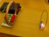
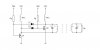
I want to know how the royer Oscillator does work there? I guess those 2 RFC's are functions of the parallel LC in the transmitter, right? And I guess the circuit is a some kind of push pull amplifier made by 2 mosfets as a halfbridge stage (Those sayings are just my GUESS and I am not sure of). Can somebody direct and clear me how the circuit does work? Is the LC in the transmitter stage makes the whole resonance freq of the transmitter?
Yes, I think the LC and Q1, Q2 make the oscillator. The RF chokes just look like a high impedance at the oscillator frequency so the fets don't short out the supply. It's a transmitter and receiver tuned to the same frequency.
What good is something like this? Instead of annoying wiring you have rigid alignment restrictions and the distance isn't enough to be useful as more than a novelty. There's a good chance that it's technically illegal because of the amount of power you're transmitting, depends on the frequency you're working with but you're probably screwing with any nearby AM radios
Well It was an interesting circuit design for me because the Maximum distance which I was able to get by my own design did not exceed to more than 5 cm!
Is here any expert to explain me how the L1 and L2 do interact to cause the circuit to oscillate? The performance of the circuit is a little confusing to me, For instance I do not sure if the L1 and L2 are affected by the copper loop in the transmitter by the magnetic fields generated by the copper loop in the nearby air, or they interact each other by the electrical circuitry? Unfortunately there is not link in the net containing the explanations of such royer circuit which basing inductors (L1 & L2 toroids) are LARGELY isolated than the main copper loop.
Do you know why the designer has used Toroids as the circuit biasing inductors?
I am sure there is an expert in the field here in this forum to explain the functioning of this royer circuit.
L1 and L2 are just RF chokes. They just present a high impedance to RF but pass DC.
The frequency of oscillation is determined by the inductance of the loop, and the capacitance across the loop.
The positive feedback for oscillation is provided by connecting the two inverting FET amplifiers in series, which effectively makes the two stages push-pull.
Ok thanks, So those L1 & L2 toroids are not AIR cupled along with the Antenna (i.e the transmitting loop), Right?
Unfortunetely I have no access to those high freq toroides, Can I take a broken PC power apart and use the insided toroids? By the why Do I need to use the just Toroids or I can use another kinds of the inductors for this?
If you read through some of these threads you will see where the topic has been touched on before in a few forms. Also, a Google of Electric Toothbrush Charger should yield some results.
If we put the receive 1/4 wavelength away from the source, both source and receiver absorb energy. The source supply EMF to receiver without energy delivered. In the meanwhile, the receiver feed EMF back to source. https://www.electro-tech-online.com/custompdfs/2011/04/11040052v1.pdf
This site uses cookies to help personalise content, tailor your experience and to keep you logged in if you register.
By continuing to use this site, you are consenting to our use of cookies.