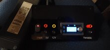
Here's a quick and dirty power supply for the bench. I do have a couple lab power supplies but often I just need power to test something quick.
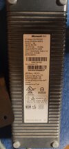
I've posted here before about XBox power supplies – 5V @ 1 amp max and 12 volts at a whopping 14+ amps. And I've also posted about power supply buck or buck/boost modules.
One of the neat features of these XBox power supplies is that the 5 volt is always on, while the 12 volt supply is controllable by a 5 volt signal.
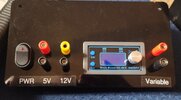
For my bench supply, I laser-cut an acrylic panel
for one of the buck/boost power supply modules, a 12V enable switch and binding posts for 5 volts, 12 volts and the variable voltage/constant current output of the power supply module. This provides fixed 5 volts at one amp, 12 volts at up to 16.5 amps, and variable voltage from 0 - 35 volts at up to 4 amps.
The power supply module was about 5 bucks from one of the Chinese vendors (there are many different versions), and the XBox supply was also about 5 bucks from a local thrift store.
The ulluminated switch is one of the type Radio Shack used to sell, designed for automotive use. It has an internal resistor, set to power the LED at 12 volts, but it's plenty bright operating at 5 volts. Note that the switch only switches a 5 volt logic level to control the 12 volt supply; it does not have to handle to ~16 amp output of the 12 volt supply.
If you say nice things, I'll post the SVG file to laser-cut the panel and a schematic showing the connections.


