Continue to Site

Welcome to our site!

Electro Tech is an online community (with over 170,000 members) who enjoy talking about and building electronic circuits, projects and gadgets. To participate you need to register. Registration is free. Click here to register now.

  • Welcome to our site! Electro Tech is an online community (with over 170,000 members) who enjoy talking about and building electronic circuits, projects and gadgets. To participate you need to register. Registration is free. Click here to register now.

Which Diode(s) Should I Use ?

Status
Not open for further replies.

ToddB74

Member
Hi All ! :)

This post was edited by ToddB74 on 7-29-2015 and again on 8-05-2015, to up-date specifications and attach my latest circuit drawing.

As explained in my original post, I built a simple Portable Outlet Box and would like to add a Red LED that will be lit when the switch is in the ON position.

The LED bulb will be a Red Super Bright, with specifications as follows:
Size : 5 mm
Lens Shape : Round
Wavelength/Color Temperature: 620-630nm
Luminous Intensity : 8000 - 10000 mcd
Viewing angle : 30 deg
Forward Voltage : 1.9 - 2.1 V
Forward Current : 20 mA
Maximum Operating Temperature : +100 C = 212 F
Minimum Operating Temperature : -20 C = -4 F

Series Resistor Ohms = 220
Series Resistor Watts = 1/4

Series Capacitor = 470 nF

Bridge Rectifier Diodes = 1N-4007

Fuse = Source : TAYDA ELECTRONICS
Manufacturer : SUNELEC
MPN : Fuse Glass F 1A 6 x 30mm
SKU: A-1017
Fuse Type : Fast Acting
Current : 1A
Voltage Rated : 250V
Material : Glass Tube
Dimension : 6x30mm

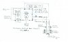
Note, on the attached up-dated circuit drawing I have indicated two possible places for the fuse, i.e. letters A and B within circles. I'm leaning toward B, but thinking it probably makes little difference. What would your choice be ? Misterbenn replied fuse location B.

Another thing I would appreciate is your critique of the above specifications and the attached drawing and letting me know if you see any problems.

Thanks for replies on the above. ;)

ToddB74
 

Attachments

  • Portable Outlet Box Circuit Sketch dated July 24, 2015 001.jpg
    Portable Outlet Box Circuit Sketch dated July 24, 2015 001.jpg
    332 KB · Views: 193
Last edited:
I'd just use a neon indicator lamp, these are able to work straight off mains voltage. google it and see if it will fit your purpose
 
There are Electrical Code requirements mandated for hard wiring AC that you ought to be aware of . Using a bridge & series R to drop 240Vdc to 1.6V means power lost in the resistor sharing the same current will be P_res.=150x P_led because of 240/1.6. At half power or 30mW, the resistor would consume, 4500 mW. Bad idea.

But using two LEDs in parallel but reversed, you can choose a series 500V rated film capacitor X1 type, that draws 10mA across 230V at 50Hz. Zc(50Hz)=23kOhm=1/(2pi*50*C)

Can you compute C?
 
Last edited:
Just **broken link removed**, and be done with it...
 
You can also get them very cheap and ready to go with leads attached from an appliance parts store, used in freezers etc.
Just drill a hole and pop them in.
Max.
 
I'd just use a neon indicator lamp, these are able to work straight off mains voltage. google it and see if it will fit your purpose

Misterbenn,
Thanks for the suggestion to use a neon indicator lamp. I hadn't thought of that and will keep it in mind for future. I googled and saw that this type lamp works on mains voltage by using a resister. Good idea and easier, however, I prefer using a LED with appropriate resister/diode. You might think I'm being silly, but more complex solutions requiring some research and the use of formulas to determine proper components is more to my liking .......more satisfying to my creative nature after the project is finished. Hope you can "dig it". ;)

Guess you could say I'm a perfectionistic, science-minded kind of guy. :rolleyes:

ToddB74
 
+1 on the Neon, also the mains input is never referred to as + & -, it is AC.
Max.

MaxHeadRoom78,
I'm studying electronics and find it fascinating !
Thanks for mentoring me on the proper term for mains input. The + and - on my circuit drawing was meant to indicate the circuit polarity, rather than the mains ; regardless, I stand corrected. :sorry:

ToddB74
 
There are Electrical Code requirements mandated for hard wiring AC that you ought to be aware of . Using a bridge & series R to drop 240Vdc to 1.6V means power lost in the resistor sharing the same current will be P_res.=150x P_led because of 240/1.6. At half power or 30mW, the resistor would consume, 4500 mW. Bad idea.

But using two LEDs in parallel but reversed, you can choose a series 500V rated film capacitor X1 type, that draws 10mA across 230V at 50Hz. Zc(50Hz)=23kOhm=1/(2pi*50*C)

Can you compute C?

Hi Tony !
I'm an electronics newbie and while I really appreciate your comments and suggestions, they are "over-my-head" at this point. No, I don't know how to compute C , as I don't know for sure what that letter represents in your particular formula. Also, I will be using regular 120V , 15 A , 60 Hz current (vis-à-vis the attached circuit sketch in my starter post) for my application here in the USA, so don't understand why you are using 240V in your reply. :confused:

Regards,
ToddB74
 
Last edited:
Just **broken link removed**, and be done with it...

Thanks MikeMl , but I would rather go with a LED for reasons explained in my reply-post #7 to Misterbenn.

I did look at the neon lamps and the selections are impressive ! Added the website to my Windows 8.1 Favorites List and might use one of those sometime in the future.

ToddB74
 
You can also get them very cheap and ready to go with leads attached from an appliance parts store, used in freezers etc.
Just drill a hole and pop them in.
Max.

Max,
Thanks again for the info.. I had some electrical work done in my home a few years back . We had the electrician add one of those little red indicator lights to a toggle switch plate in our laundry room to alert us when we forget to turn the garage ceiling lights OFF. A quick glance at the switch plate when in the kitchen often saves a walk to the other end of the laundry room. Convenience ! :smug:

ToddB74
 
Last edited:
Because of the hazards involved with shock and fire, and the specialized parts required, this is not a project for a newbie.
 
I'm an electronics newbie and while I really appreciate your comments and suggestions, they are "over-my-head" at this point.

Its exactly because you are a newbie that everyone is suggesting neon lamps.

Don't get me wrong I encourage learning, but this is a potentially dangerous project to start off on. Unless you use a isolation transformer (and i suspect you wont due to complexity and size) you are talking about a mains connected circuit without a proper understanding of electrical safety and component failure modes. You could hurt yourself on this endeavor, but to be honest that's not what I'm concerned about. If you hurt yourself well that's your own fault but the set up you suggest could be used by a layman (general person) and hurt them and that's far more concerning.

If you want to learn I suggest getting a 230V to 12 or 24Vac step down transformer and fast blow low current <<1A ouput fuse. This will let you create practice circuits and develop understanding while not endangering yourself or anyone else.

If you want a quick solution which is quick and for the most part safe (not completely because the neon could have exposed wires if your enclosure isn't very good or not grounded correctly), then just buy a neon.

Again i just want to say i encourage learning and if you're proceeding safely I'm sure we'll all be happy to help guide you. But main's voltage is not something a "electronics newbie" should be playing with and its certainly not suitable for just lifting a circuit off a forum without deep understanding of what you are doing.
 
Which wears out sooner, a neon indicator light bulb or an LED?
1) My freezer is about 30 years old and its neon light bub flickered for the past few years and now does not light any more.
2) My first clock radio is about 30 years old and its red LED display has gradually got dimmer and dimmer and now can barely be seen in shaded daylight. Years ago I added green LEDs on each side of its radio dial and now they are also very dim.
Its power supply still works perfectly.
 
Its exactly because you are a newbie that everyone is suggesting neon lamps.

Don't get me wrong I encourage learning, but this is a potentially dangerous project to start off on. Unless you use a isolation transformer (and i suspect you wont due to complexity and size) you are talking about a mains connected circuit without a proper understanding of electrical safety and component failure modes. You could hurt yourself on this endeavor, but to be honest that's not what I'm concerned about. If you hurt yourself well that's your own fault but the set up you suggest could be used by a layman (general person) and hurt them and that's far more concerning.

If you want to learn I suggest getting a 230V to 12 or 24Vac step down transformer and fast blow low current <<1A ouput fuse. This will let you create practice circuits and develop understanding while not endangering yourself or anyone else.

If you want a quick solution which is quick and for the most part safe (not completely because the neon could have exposed wires if your enclosure isn't very good or not grounded correctly), then just buy a neon.

Again i just want to say i encourage learning and if you're proceeding safely I'm sure we'll all be happy to help guide you. But main's voltage is not something a "electronics newbie" should be playing with and its certainly not suitable for just lifting a circuit off a forum without deep understanding of what you are doing.


Misterbenn,

I appreciate the concern for safety expressed in your post #13 and fully agree.

Unfortunately, I allowed myself to get in too much of a hurry when designing /making the Portable Outlet Box and knew better at the time, but went ahead and used a 2-wire lamp cord with no ground wire. That was a mistake and probably what "spooked" you and others when viewing my circuit sketch......and justifiably so. Then when I admitted to being a newbie in a subsequent post, that was the "clincher" ! However, let me explain. While I am a newbie to electronics, I am no stranger to the basic fundamentals and safety requirements when working with electricity. I hope the following will help to raise your confidence in my knowledge when working with electricity.

As for the circuit sketch attached to my starter post, I am going to re-design that circuit to use a different power cord that includes an earth (green colored) ground wire for attachment to the duplex outlet metal frame (normally not current-carrying unless there is a fault) and plug with ground tang. Also, since I'm using a plastic receptacle box and cover plate, even if a short happens inside the box no current can reach a human hand or other material touching the box, anymore than would a store-bought outlet bar with plastic enclosure.

I am age 74 and have been interested in science and electrical projects in particular from an early age. In 1970, at age 29 , with full-time employment, owning a home and raising children, I decided to take a home-study course in electricity and appliance repair offered by the National Radio Institute in Washington, DC. Finances were tight and this allowed me to save money doing my own electrical repairs on small and large appliances, adding simple electric circuits for lights and outlets, replacing faulty wall switches and the list goes on.

The NRI course of study included atomic theory and building my own VOM from a kit that required solder connections for analog Volt-Ohm and Amp meters, resistors, potentiometer and many other components too numerous to list here. This VOM is still working today and I use it once in a while, but normally use a modern DMM. I also have several soldering irons of various wattages acquired over the years and a Hakko Digital Soldering Station FX-888D purchased more recently with a matching Soldering Iron FX-8801 for more precise control when soldering tiny electronic components arranged close together on a PCB.

Returning to my early years, after completing the NRI course, one of my first serious endeavors was to design and install a complete electrical system for my father's barn after it was built. This included a breaker panel, electrical outlets, toggle switches and ceiling lights in several sections of the barn. There was never a problem with that system. ;)

On two other occasions I helped my mother and later a neighbor when their refrigerators failed to run. I built a tester (circuit from NRI course book) to by-pass the magnetic relay switch and see if the compressor could be jump-started and when the compressors did start in both cases, I installed a new magnetic relay switch.....voila !......that put them back in business ! The satisfaction of using my knowledge to help others was payment enough !

In my desire to learn about electronics, I have learned much from Internet websites and have purchased several electronics tutorial books online. Two of these that stand out IMO are listed below.

  • Getting Started in Electronics, by author Forrest M. Mims III
  • Make: Electronics, Learning by Discovery, by author Charles Platt
The "Make" book helps students to learn, with knowledge and forethought of course, by deliberately causing component failures. A novel approach IMO !

To conclude, I hope you and others are now more inclined to freely pass-along information to help me advance and complete my electronics projects. If I don't understand something, I'll admit it and not proceed with "hands-on" work until I do.

I still want to use the red LED described in my starter-post, with appropriate resistor and diode components and if you now agree, would appreciate answers to the questions requested in my following paragraph (copied, pasted and colored here for your reference).

I want to incorporate a diode(s) in the circuit, not only to convert AC to DC voltage for the LED, but to protect it from the possibility of reverse voltages. Should I use low volt & current "Signal" diode(s), rectifier diode(s), or a bridge rectifier, etc. ? Also, what diode number would that be ?


Thanks very much !

ToddB74
 
Last edited:
ToddB74,
I can understand the concerns about you safety by people replying to your post. In your first post you label an AC supply with + and -. You have no earth connections and you use an internet calculator for a simple thing like calculating the value of the series resistor for an LED. When someone mentions the use of + and - you say it is to indicate polarity. The polarity of an AC supply reverses every 8.3 mS (Assuming a 60 HZ supply.)

Les.
 
Thanks ToddB74, Its always helpful to have an understanding of a persons background and experience. I always start off by assuming the OP is a school student.

Tony has given you the start of an answer here.
But using two LEDs in parallel but reversed, you can choose a series 500V rated film capacitor X1 type, that draws 10mA across 230V at 50Hz. Zc(50Hz)=23kOhm=1/(2pi*50*C)

This link should help http://www.marcspages.co.uk/tech/6103.htm
 
Thanks ToddB74, Its always helpful to have an understanding of a persons background and experience. I always start off by assuming the OP is a school student.

Tony has given you the start of an answer here.


This link should help http://www.marcspages.co.uk/tech/6103.htm

Misterbenn,

Thanks for the link ! :)

A "school student" I'm not, however, some of our greatest inventors were self taught.

I copied and printed the bridge rectifier circuit drawing and all relative text, including the NOTES at the bottom of Marc's document. After digesting this and making final decisions on the exact components I want to use, I'll accumulate these components and temporarily install them on a breadboard for testing before building the final pcb and incorporating it with my Portable Outlet Box circuit.

I'll report the results here after completion.

Your help is greatly appreciated my friend and thanks again for trusting me to use the information wisely ! ;)

ToddB74
 
Just a note on your test setup. Breadboard is not designed for hv and i suspect will have corona if not actual arcing.

I suggest using veroboard for the proto with some copper tracks scrapped off.

Also make sure to use a fuse, but I'm sure you know that.
 
Status
Not open for further replies.

Latest threads

New Articles From Microcontroller Tips

Back
Top