Continue to Site

Welcome to our site!

Electro Tech is an online community (with over 170,000 members) who enjoy talking about and building electronic circuits, projects and gadgets. To participate you need to register. Registration is free. Click here to register now.

  • Welcome to our site! Electro Tech is an online community (with over 170,000 members) who enjoy talking about and building electronic circuits, projects and gadgets. To participate you need to register. Registration is free. Click here to register now.

Which Diode(s) Should I Use ?

Status
Not open for further replies.
The other interesting and useless bit of information about neon tube indicators is they are negative resistance devices like DIAC's but at a higher voltage and only one lead glows when used on DC.

Hummmm........Maybe "useless" as you say Tony, but nevertheless interesting to me ! ;)

Thanks for the info.

ToddB74
 
Hi All ! :)

If you are familiar with this thread, you know I'm designing a circuit for a 5mm Super-Bright Red LED. The primary power source will be 120V, 15A , 60 Hz, full-wave AC current, changed to DC for the LED, using a bridge rectifier, with a resistor in series with the neutral circuit wire and a capacitor in series with the hot wire and both of these components connected ahead of (prior to) the bridge rectifier. The LED is in the bridge rectifier circuit of course.

In addition, this led circuit will be protected by a 'Fast-Acting' glass fuse rated for 1 Amp connected in series on the hot wire side, but where exactly in the LED circuit should the fuse be connected ? I know the fuse should go on the hot side, but ahead of (prior to) the capacitor, after the cap or somewhere else in the hot line.......dunno ! :confused:

I have deliberately given a general description of the circuit without any component specifications, thinking that since my question is only concerned with the topographical positioning of the fuse, you would not need the values of any components to answer this.

Thanks in advance for your help.

ToddB74
 
Last edited:
Put the fuse right at the incoming power to your circuit, so before the cap and all other components.

You want the fuse to protect the whole circuit, so for example if the cap shorts to chassis or if the resistor fails short it shouldn't matter the fuse will be there to disconnect the supply
 
Misterbenn,

Thanks for your reply re where to put the fuse in my circuit.

Attached is my latest circuit drawing below.

Note, I have indicated two possibilities, i.e. A and B within circles, that I think you mean, but not sure which one.

Please advise.

Thanks,

ToddB74
 

Attachments

  • Portable Outlet Box Circuit Sketch dated July 24, 2015 001.jpg
    Portable Outlet Box Circuit Sketch dated July 24, 2015 001.jpg
    194 KB · Views: 143
Well a neon is fine but still need a limiting resistor they are after all only 90 volts. I f you want a led then you need a blocking diode in series a voltage divider to insure the led will not break down they are diodes anyway but lousy diodes. for 120 v you need to waste power to get to the led forward voltage plus the current required to light it. Do the math. 120v /.010I for the led~2.8 V across the led.
rectifiers are good for hi reverse voltage blocking however they do have a lousy saturation current.
signal diodes have a very good blocking capabilities however the reverse voltages are very low in addition cannot carry much forward current.
 
Last edited:
Well a neon is fine but still need a limiting resistor they are after all only 90 volts. I f you want a led then you need a blocking diode in series a voltage divider to insure the led will not break down they are diodes anyway but lousy diodes. for 120 v you need to waste power to get to the led forward voltage plus the current required to light it. Do the math. 120v /.010I for the led~2.8 V across the led.
rectifiers are good for hi reverse voltage blocking however they do have a lousy saturation current.
signal diodes have a very good blocking capabilities however the reverse voltages are very low in addition cannot carry much forward current.

analog1,

Thanks for the information , but I'm not expert enough in electronics to evaluate and apply it to my project.

In other words, I can understand bits and pieces of your information, but not able to render a final conclusion from it and then use that conclusion to make decisions on my project.

As admitted earlier in this thread, I'm an electronics newbie and fixated on understanding and using low-volt single LEDs as indicator lights for current and future projects, rather than using neon bulbs. The attached sketch with my previous post #44 shows my circuit, as now designed, for reference.

Although I do appreciate the efforts of members to open my eyes to more facts and approaches, I'm getting over-saturated and confused and would like to keep the focus on answers I can use to finish my current project. Naturally, if I'm making any mistakes, I welcome critiques. ;)

ToddB74
 
Some power strips use LEDs. This one does:- **broken link removed**

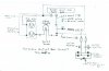
The indicator was flickering quite noticeably, so I had a look inside. There are four LEDs around the switch button, and they are run from a resistive dropper and a diode with around 1 mA. There was no smoothing, so the flicker was 50 Hz, which is really obvious to me.

Also, the four LEDs are in two strings, each with a resistor. The four LEDs are evenly spread around the switch, at 90° gaps. One string contains the two LEDs at the 0° and 180° positions, and the other has the 90° and 270° positions. The two strings are also the same polarity, so they light on the same half of the mains cycle. Any idea why the design with two strings, which therefore uses twice the power? Could it be that it was intended to have the two strings on opposite polarities to reduce flicker?

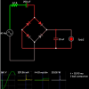
I've changed my one to a single string and added a smoothing capacitor.
 
Everybody Please Note !

My first post has been edited (on 7-29-2015 and again on 8-05-2015) to up-date specifications and attach my latest circuit drawing.
So please see my first post on page #1 before making further replies.


Thank you ! ;)


ToddB74
 
Last edited:
Hi Todd,

I've not simulated your circuit to check the current ratings and such but from looking at your updated post I have the following comments:

  • Position B is good for the fuse, this will protect the LED circuit. If you were to install it at A it would limit the current of your outlet box to 1A
  • The diodes 1N4007 are fine, probably slightly overkill as you could get away with a lower reverse voltage value, 1N4004 would be fine but doesn't really offer any benefits. With the 1N4007 you'll have more headroom for inductive voltage spikes. So what i'm saying is 1N4007 is fine but if you cant get it anything down to 1N4004 would be ok.
    • the diode has a fuse rating of 3.7 A^2S, this is a measure of the power required to kill the diode in the event of a short circuit for example. You want the fuse's fuse rating to be lower than this so it blows first! You haven't specified the exact fuse your using but looking at other fast acting 1A fuses they have an fuse energy around 1.4 A^2S so this is good.
    • The fuse will increase in temperature by 50 degrees for every watt of energy dissipated. You should check that this is acceptable. Calculate the energy dissipated by the diodes using the forward voltage drop 1.1V multiplied by the expected RMS current (lets assume 1A as thats the fuse rating, although if your circuit works correctly the current will be much less) so 1.1 x 1 =1.1W. Divide this by two as each diode only conducts for half an AC cycle. So each diode will have a temperature rise of 0.55 x 50 = 27.5 degrees. This is absolutely fine but diodes may feel slightly warm to the touch, but only touch them if you've removed the power!
  • We need more details about the capacitor, like the type of capacitor (should be a film type), voltage rating, current rating, frequency response. If you give us a part number we can go through all this. If you are still looking then i suggest searching for X capacitors, these are designed for mains use.

Good luck

**Edit, a few additional thoughts:**
Marc on this page http://www.marcspages.co.uk/tech/6103.htm also notes
There have been reports of people getting a rather large 'sting' from this circuit when used as a 'night light' (not its intended purpose!) when uplugging it from the mains. Reason is, the capacitor remains charged and their hand completes the circuit. The cure is to take two 470k resistors in series (so as to form one 940k resistor) and place this across the cap. This will discharge the cap within a short space of time thus removing its sting.

I just noticed that the values you are using match the ones on Marc's page. I need to point out that his values are intended for 50Hz 230Vac operation so wont translate across. Using these values you can expect about half the current (16mA rms, 23mApk) luckily for you this is almost perfect for the LED you selected.
A further benefit of this is that your resistor will have plenty of power headroom as the resistor power dissipation is related to the square of the current. But still, make sure you get a wire wound type.

**Further edit. ***

As I've now worked out the actual circuit current i though i might as well update the diode heating calculation.
1.1V x 0.02A = 22mW.
0.022W / 2 x 50 = 0.6 degrees
so very low heating in the diodes. :)
 
Last edited:
Many "super bright" LEDs are ordinary dim LEDs in a case that focusses the light into a narrow angle. Then it cannot be seen unless it points directly towards you. So you should use an LED with a wide angle.
 
Unfortunately the series cap alone can cause large currents thru the LED if power is turned on at the negative peak -160Vp of the 120V AC line.

It would be random , but one time it will blow the LED with a spike of 160V/220Ohm or almost an Amp.

You must lower the current and reduce C by 50% and raise R to limit the charge current for worst case turn on. 160V/1k2 = 133 mA peak is still too high for most 5mm LEDs

upload_2015-7-17_18-53-13-png.93351


upload_2015-8-1_11-21-21.png

SHown above is the peak Vin , Peak current to LED and peak power in the resistor.

Note also the Resistor must be WW to handle these peaks not film R and the cap must be X1 rated plastic.
 

Attachments

  • upload_2015-8-1_11-19-17.png
    upload_2015-8-1_11-19-17.png
    11.2 KB · Views: 141
Last edited:
Hi All ! :)

Due to my wife and I both experiencing declining health in our senior years, we are forced to give up our self-employed business, sell our home and move into senior housing. This needs to take place during the next several months or so.

We will be concentrating our efforts on making the move, so I won't have time for hobbies and regret to advise everyone that I must abandon this Portable Outlet Box project for now.
After we get resettled, I'll try to continue work on this project and resume communicating here.

So, a BIG THANKS to Misterbenn and Tony Stewart who have given so much of their time posting replies to help me.

My appreciation also goes out to the following for their efforts to help.

audioguru, Les Jones, MaxHeadRoom78, MikeMI, analog1 and Diver300

Best Regards !

ToddB74
 
Good day everyone!
For mains power indicator light, I still prefer the old tech component -- small glass neon bulb (NE-2, 6mm diameter) . But instead in series with a fixed value resistor (normally 100K to 200Kohm), I use a 400V polyester capacitor in series with the neon bulb. This setup has few advantages : (1) consumes lesser power. Only the neon bulb (about 0.030W) does as the capacitor does not consumes any. (2) The cap will filter off the high frequency noise from the mains lines. Especially when there are switching mode handphone chargers around. (3) The neon bulb will absorb high voltage spikes/surges from the mains lines.
I chose 0.033uF (about Xc= 100Kohm) in series with a common 6mm dia neon bulb and run 24 hours for about 6 months so far. The only problem I have found is the neon bulb getting dimmer recently. May be the series capacitor should be fine tuned for its value.
Appreciate your comment on my neon bulb in series with capacitor ..... Thanks
 
The neon bulb on my freezer stopped lighting after about 5 years. The LED display on my first clock radio still lights dimly after 45 years. Their currents are limited with resistors.

A series capacitor filters away low frequencies but passes high frequencies. Voltage spikes are high frequencies. Then the neon bulb has nothing to limit the current from voltage spikes and is doomed.
 
Cap is a bad idea since it is a high pass filter and short to fast rise surge pulses
 
Ok im dialectic my problem is eg i revers things i fot to put it up look at leavee than i pull down a paet from that i aint no dum dum ass i xan build anything from nothing only started learning electricala last 3 yrs. Nut i cant remember nouns unts why all the gils when clubing where hi beauthi cutie hay sexy hiw you doing gorgeous hay girl and hi babe. Any how the way i learn is reversed can s9mw one answer a. What resistor do i need on a 12volt 2 amp line. And on a 3.5 /4 volt line with about .8 amps i need the aquaetoin and completed sum and the resistor colour code so i xan copy it so i may learn it in reverse.
Like i allready yous me pjone with a app that allows both carma's to work and a app that starts taking snap shots and emails them to me all wil3 using a fox tell dish and using macca' wifi and mybhouse alarm is screeamers 9v on a 12 volt surply and every door has car door light switches on them inside and the old school see shell horns out side. And my tolit runs on dam water that i wiered up to a car fuil gage reeder just minutes the top1/4 of the reader so the solouar pump will turn off. So see i aint no dumb ass i just rwaly learn diffrently
 
Status
Not open for further replies.

Latest threads

New Articles From Microcontroller Tips

Back
Top