Electro Tech is an online community (with over 170,000 members) who enjoy talking about and building electronic circuits, projects and gadgets. To participate you need to register. Registration is free. Click here to register now.
Welcome to our site! Electro Tech is an online community (with over 170,000 members) who enjoy talking about and building electronic circuits, projects and gadgets. To participate you need to register. Registration is free. Click here to register now.
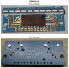
These modules were made many years ago, I stll have four with the LM3915 logarithmic IC. They have the dimmest LEDs ever made.
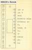
I have a pic and a terminals layout. Here is the pic:
If I remember right, Radio Shack used to sell those.. I think it was there I got one in the mid 1970's. I agree, the LED's were terrible. Better to just do the circuit yourself with one of the IC ( LM3915 , LM3914, LM3916 )and separate LED's.
audioguru: is that a Forrest Mimms "Engineer Note" ?
It looks like that book that RadioShack also sold. I might have the book on my hard drive but I found the NSM info recently with a search on Google, one page has a coffee stain on it.
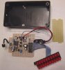
I agree that an ordinary 18 pin IC and a 10-LED lightstrip is easy like in my project (I used two LEDs in series to make it look like stereo):
They are available in a surface-mount package, but its heat dissipation is too low for most applications. Its 10 output transistors are current regulators that eliminate the need for 10 current-limiting resistors for the LEDs. With the surface-mount package you could operate the output transistors saturated for them to be cool, then add 10 regular resistors or a 20 pin resistors package.
Not sure why you would need such precision in that range?
And Only if you can actually Convert the Specific LED Displays to the specific dB.
dB is Not Linear, (1,2,3,4,5........) it is a Doubling of Voltages. (1,2,4,8,16.......)
Simple: to be able to accurately set loudness and also detect signal clipping. I don't care about signals below -10dB or beyond +6 when my objective is to accurately set recording level so all tracks sound the same loudness.
And Only if you can actually Convert the Specific LED Displays to the specific dB.
dB is Not Linear, (1,2,3,4,5........) it is a Doubling of Voltages. (1,2,4,8,16.......)
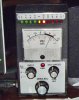
I didn't have to convert anything, just adjust the signal level. Signal step levels do not double on each step, they increase by 0.125V in my design. DB levels are listed next to the part. The design would be useless if it had 3dB steps as there would be no usable accuracy.
Bountyhunter;
I see what you are doing...instead of having a single "peak led" you have an array that warns you when the signal level is getting close to that peak.
Very Nice!
This site uses cookies to help personalise content, tailor your experience and to keep you logged in if you register.
By continuing to use this site, you are consenting to our use of cookies.