Continue to Site

Welcome to our site!

Electro Tech is an online community (with over 170,000 members) who enjoy talking about and building electronic circuits, projects and gadgets. To participate you need to register. Registration is free. Click here to register now.

  • Welcome to our site! Electro Tech is an online community (with over 170,000 members) who enjoy talking about and building electronic circuits, projects and gadgets. To participate you need to register. Registration is free. Click here to register now.

Where to find a parabolic dish?

Status
Not open for further replies.
ShortCircuit Posted: Fri May 06, 2005 1:42 pm Post subject:
--------------------------------------------------------------------------------
Almost...here is the dish I'm talikng about.I want to use the existing arm where the LNB is connected to use as my microphone mount.I was wondering if the parabola is a good shape.

Yes that dish will work Very well.
The Microphone goes Exactially where the LNB was mounted, But Ideally inside an Inverted Cup to Prevent Unwanted Noise from coming in from the sides.
The only problem is aiming that dish. Typically the Aiming direction is at the Opposite angle to were the LNB is Mounted.

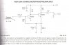
To make a Good Parabolic Mic, Ideally you will also make a Good Amplifier for it, as well as Some Filters to get rid of Unwanted Noise.
An Adjustable Bandpass filter is useful, so are Low and High Pass Filters.

Take care..........Gary
 
Just want to get someone's input, is this a good parabolic mic amplifier? I like it because i already have all the components to make it :lol:
 

Attachments

  • high_gain_mic.gif
    high_gain_mic.gif
    57 KB · Views: 743
Zach, Couldn't you get the Picture ANY BIGGER?
I had to save it to my harddrive and reduce it, to see it at a Reasonable Size.

Yes it should be OK, But as I said before, A Bandpass Filter is a Really good idea. And on that Preamp I would connect it between the two stages of the IC.
 
I tried using an offset dish for this a while ago and had no luck with it. I'm sure it needs to be a prime-focus dish to work well. Every one I've ever seen has used a prime-focus dish.
 
holy smokes, thats huge! i forgot how huge it was, its been on my computer for a while. sorry about that :lol:
 
It's alright on a 30" screen placed in the window being viewed from the bottom of the garden.

:D
 
TV-Engineer, I tried using an offset dish for this a while ago and had no luck with it. I'm sure it needs to be a prime-focus dish to work well. Every one I've ever seen has used a prime-focus dish.

I am using one of those offset satellite dishes and Getting Very good results. The Focal Point on Any GOOD Dish is Always Critical. A Better Parabolic Mic uses Two Parabolics. The Second one is Tiny and Behind the Mic. It Catches any missed sounds and sends it back to the main dish to be reflected again.

But I'll Admit, Aiming it isn't as nice as a Straight on Focus type dish.

I also have a 6 Foot Aluminum type, straight on dish, Its Excellent, Except Portability is a bit of a problem. Especially through Doorways.

In a few weeks I hope to have a Custom made Mould for a more suitable, Straight on dish. A Friend of mine will than Vacuum Form me some Parabolics using ABS Plastic from this mould.
If you looked at my Website Article, (Link is Above, May 5 post) The Mould will be cast from the Glass Parabolic shown there and than Extended to about 15 inches diameter. That Glass parabolic is from a WW2 Navy Distroyer. VERY PRECISION.
 
Sorry Chemelec, I somehow managed to miss the first page of this topic entirely! :oops:

I'm going to your site now. I wouldn't have added my two pennies worth if I'd seen the first page, since it covers what works and what doesn't...
 
TV-Engineer Sorry Chemelec, I somehow managed to miss the first page of this topic entirely!

I'm going to your site now. I wouldn't have added my two pennies worth if I'd seen the first page, since it covers what works and what doesn't...

It Not a Problem, I Screw up Quite Often Also.
But I have done a Lot of expermenting with Parabolic and Shotgun Mikes.

The Article on my Site is a Fairly simple one that Quite easy for others to make. However it works fairly well.
But I have done up some Very Soficated designs as well.

Take care..........Gary
 
Hey Gary,
He, he. You must be very sophisticated to be able to do up Sofisticated designs. :lol: :lol:
 
I have built that amplifier in the schematic above.It is sensitive, but it also has alot of noise in it.I thought the LM387 would be a good one to use.After the noise,I used an NTE replacement just to see if it was the original IC or what.After replacing it with the NTE cross-reference,it had the same noise level as before.I did a search on this site(which is great by the way)and found this circuit.It looks pretty simple and might do the trick.I like ICs,don't get me wrong.But I also like a simple approach as well.Any inputs on this circuit.I have got some 2N3904s around and I know the hfe on each is 242 to 245.Any way to calculate the gain knowing the hfe's of the transistors?

SC
 

Attachments

  • preamp_109.jpg
    preamp_109.jpg
    48.9 KB · Views: 650
Both the LM387 and the two-transistor circuits have a gain of about 3,200 but the transistor circuit would load-down an electret mic less, and therefore be more sensitive. That is a very high gain, maybe the noise is from the Jfet inside the electret mic. :)
 
I did'nt think of trying a different microphone other than an electret.Dang,wish I had kept the circuit now.Live and learn I guess.I looked at chemelc's website.I LIKE THAT ONE.I noticed he had a plan to use a speaker as a microphone.The thought of more area coverage is appealing but I might have to sacrfice sensitivity.If I used the speaker-as-microphone circuit instead of a electret mike and given the speaker was an 8 ohm load,would the circuit,once built,have an output of 8 ohms or would the load be higher like that of an electret microphone?I was reading the text under the schematic I attached.The gain is determined by the sum of the 2 transistors' hfe,which are 242 each(hfe1+hfe2=484)times the ratio between the input and output load.The output being 10k.So would'nt a lower load(the 8 ohm for example)make the gain higher since there is a greater ratio between the input and output?Man,this is fun!!!!

SC
 
ShortCircuit said:
I LIKE THAT ONE. I noticed he had a plan to use a speaker as a microphone.The thought of more area coverage is appealing but I might have to sacrfice sensitivity.
I have noticed that most speakers small enough to be a microphone have a high resonance frequency and make a boomy and screechy sound like the ones at gas stations. You can't blame all the poor quality on the tin can they use for an enclosure.

I was reading the text under the schematic I attached. The gain is determined by the sum of the 2 transistors' hfe, which are 242 each(hfe1+hfe2=484) times the ratio between the input and output load.
The text says the gain is the product not the sum of the transistors' hfe but I don't believe it since the transistors each have an hfe of about 220 and thefore the calculation is 48,400 which is impossible. The low input impedance of the 2nd transistor loads-down and decreases the gain of the 1st transistor. I think the circuit's gain will be only the sum of the transistors' hfe as you say, about 440.

So would'nt a lower load(the 8 ohm for example)make the gain higher since there is a greater ratio between the input and output?
No. I don't think the circuit's gain has anything to do with the ratio.
The circuit's input impedance is 3k to 5k and is not the same as the mic impedance, except a very high impedance mic would be loaded down by the circuit's 3k to 5k. A very low impedance mic wouldn't be loaded down and would provide its full output. A 3k to 5k mic like an electret would have its output cut in half.

The gain of the 2nd transistor is max with no external load and is cut in half with a 4.7K load. A 510 ohm load would cut the gain to 1/10th.

Bootstrapping a transistor and an emitter-follower for its load can provide a very high gain. But it's late here now and it is another story.
SURE IT'S FUN! :lol: :lol:
 
audioguru Wrote: I have noticed that most speakers small enough to be a microphone have a high resonance frequency and make a boomy and screechy sound like the ones at gas stations. You can't blame all the poor quality on the tin can they use for an enclosure

Actually the Sound Quality I got was Very Good.

Most small speaker Won't detect Really Low sounds or Very High Sounds. But I found the Midrange 500 to about 5000 Hz is quite good.
 
Gee...I think the transistors are giving me a headache now.LOL.Anyone got a good schematic for using an opamp as a high gain mike preamp?

SC

p.s...If something shocks ya...unplug it.....THEN kick the crap out of it.LOL
 
I'm Curious, Why are the Transistors Giving you a Headache?

Those circuits are So Simple.
Even the 3 transistor one on my site is easy to make if you have the circuit board.

If its really a problem I can mail you one for my design.

Gary
 
Hi Gary,
I've been there before but now I can't find it. Where's the link to your website?
 
Here is another place to look possibly, from the guy who wrote the book "Electronic Gadgets for the Evil Genius," which includes, by the way, plans for building a couple of listening devices.

Information Unlimited: Listening Devices

I admit that I have no experience in dealing with them and as such, cannot personally recommend them, though others may have had some experience.

Edit: I had thought that I had seen them selling just the parabolic dishes, but I cannot find them any longer. I only see complete kits or plans. Perhaps they've been moved.
 
Status
Not open for further replies.

Latest threads

New Articles From Microcontroller Tips

Back
Top