I live in 120V land not 220V.
A sine wave inverter will have a 120 RMS and a peak of 160 volts.
A square wave will have +120 and -120 and no other voltage.
I have seen inverters that have a wave like this: 0, 0, 160, 0, 0, -160, 0, 0 The idea is, the peak needs to be 160 for the products that live off of peak and have a average of 120 for things like heating elements.
In this case you will have a time with no MOSFETs on, Top MOSFET on, no MOSFETs on, Bottom MOSFET on.
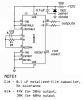
Last time I made one of these I used a CD4017 counter to get the timing.