Continue to Site

Welcome to our site!

Electro Tech is an online community (with over 170,000 members) who enjoy talking about and building electronic circuits, projects and gadgets. To participate you need to register. Registration is free. Click here to register now.

  • Welcome to our site! Electro Tech is an online community (with over 170,000 members) who enjoy talking about and building electronic circuits, projects and gadgets. To participate you need to register. Registration is free. Click here to register now.

What's the difference controlling a 180v PMDC motor to controlling a 12v PMDC motor?

Status
Not open for further replies.
Hi Mate, I also wondered if I could derive the actual RPM from somewhere as the TM used to show KPH so I may be able to find the RPM somewhere?

Al
 
Yo,

thought I'd chime in so that people following the post can keep up!

As I said to Al, although there is no guarantee of making a workable 'fudge' solution by just using the control lines, and can be a lot of boring work.. it is always rewarding to leave an entire system 'intact', as then all the safety measures are still in place, and makes things less likely to go 'pop'. But of course its by no means 'the best' way ('best' being quickest/cheapest/easiest). I guess we all have our specialist area, which biases us towards solutions involving those - mine being data comms :)

I was hoping this thread would continue with other ideas so Al had lots of opinions and options. All I'm doing is posting about working out the data sent too and from the control board in the hope that some of the functionality he doesn't want to use, is provided by the controller boards micro, which he can replace with a smaller micro that just doesn't send that info. Can be a real hassle, but maybe worth it.

I didn't mean to side-step the thread with talk of logic analyzers, serial protocols, when the options of rebuilding, or hacking the board itself (removing micro, and some circuitry, but leaving a lot in place) are just as valid, if not a better way.
I'm sure Al will keep you guys up to date on things!

Scott
 
No problem Scott. Better chance for success with the fewest possible changes. My only idea had to do with the speed connector. Al said when he turned the pot to the end when connected to this it would either speed up or slow down. My thought was that perhaps this was just a pulse up and pulse down control. If it is he could build a simple circuit to pulse it and leave the board intact. If that one doesn't work, I'm in hack it mode, because I don't know much about micros. :D
 
Hi Ron,
The pot when connected only worked on full deflection and does indeed turn the speed up and down but exactly the same as a switch held down, and maybe I didn't mention that I had to turn the pots connections around to reverse the effect, so for certain it would work with simple pulses, but then I would have to press start then wait for the damn annoying 3 second beepy countdown even before I could begin pulsing the circuit. Thats the problem, getting past the wait. If the motor would only get turned on once in a blue moon I could cope with the wait but with most machines it will be on and off like a tory's promises.

Any out of the box suggestions are welcome and if I have to I will make one of the controllers posted earlier. To hedge my bets I have acquired the components needed, they will always come in if I don't use them now. :)

Al
 
Hi Scott, here is the pic of my devman. That is with the CP2102 plugged in and light on and connected to my analyzer.

Al
 

Attachments

  • mydevman.jpg
    mydevman.jpg
    205.5 KB · Views: 162
Looks fine to me! Com10 it is, sadly, I have so many USB-serial bridges... FTDI, siliconlabs, AVR, my own homerolled ones.. that my poor PC is on.. Com23 now...

Good call on the options in windows for power control. On laptops especially to save draining the battery, they often default to 'low power', which means windows turns off power to USB unless you tell it not to. Annoying at best.
 
P1080425A_resize.JPG
P1080424_resize.JPG
P1080423_resize.JPG
Hi Scott, More Pics as promised.

Al
 

Attachments

  • P1080427_resize.JPG
    P1080427_resize.JPG
    698.7 KB · Views: 143
  • P1080426A_resize.JPG
    P1080426A_resize.JPG
    802.6 KB · Views: 142
  • P1080428_resize.JPG
    P1080428_resize.JPG
    666.5 KB · Views: 133
  • P1080429_resize.JPG
    P1080429_resize.JPG
    670.7 KB · Views: 129
  • P1080430_resize.JPG
    P1080430_resize.JPG
    612 KB · Views: 142
Just an update to keep this thread alive.

Al sent me the boards, sans motor (the postage would be astronomical..).
I've traced out a schem of the motor control board, and the 'front end' of the display board (which just uses transistors for level conversion from TTL to the ~12V bus).

Please note: The two lines going between the control board, and display board are digital (opto isolated) and both go to the on-board micro. These aren't direct PWM signals.

The good news is when the 'start' button is pressed on the display board, nothing is sent to the controller board - the annoying countdown which delays start-up is all down to the display board. As soon as it finishes its countdown, it starts a signal to the controller board, which turns on the relay to the main power supply, and starts PWM. The controller board also sends a signal back during operation, which I can only assume is a 'tach' signal indicating motor speed. There is no opto sensor input - the connector footprint isn't populated, so I'm assuming it uses back EMF, motor+/- voltages, and current measurements to get its RPM.

I was way off when I thought these were serial-type data bytes. They are both a form of PWM, that seem to 'embed' data in them. I don't have the motor attached so often (95% of the time...) the display board will come up with an error code (E01, E02) probably because no current is drawn, and the motor voltage is high (nothing to load it down). Because of this, I cannot get the display board to send out its 'commands' (or even view the frequency/duty) of the signal it sends to the controller - it expects a return signal of unknown ferquency/duty, and possibly will embedded commands. Without this signal, I have no way of knowing what signal the controller board needs >>. And I'm afraid I don't happen to have a 1.25HP motor to hand :D

I knocked up a tiny little variable frequency/duty generator with a PIC16F675, using pots to adjust both values, just to see if I could hit on roughly the sort of signal it expects, alas, without the motor control board, I get error codes most of the time, but occasionally, around ~240Hz @ 66% duty, its happy. And pumps out 150Hz (with a jumping duty cycle, it skips pulses).

Anyone know roughly the sorts of signals that go to and from motor controller boards, and display boards? I'm unsure if its proprietary or a known standard (like PWM, that skips pulses to embed data). Was hoping it was either serial, which is easy to sniff, or constant PWM.
 
Another update - although I suspect no-one is really watching this thread anymore except the OP :)

The console board sends out 'packets', in a similar format to what remote control IC's use - PWM with 33% duty representing one bit, and 66% duty representing the other. 13 bits sent in a small packet, two types of packets sent, each one sent twice.

So, who'd have thunk it! Its not serial, not RS422, not CANbus, or standard PWM. Should be easy enough to knock up a controller using a PIC for the OP. If anyone else is attempting to re-use treadmill motor-controller boards that don't use simple PWM as sped control, I'll post the full protocol here - any how to debug it.
 
I'm still watching
 
Righty!

I'll try to keep it short.

After knocking up a variable frequency/duty oscillator with a wee 8-pin PIC and tweaking it until the console board is happy, I recorded the output
of the console with audacity as a crude deep storage oscilloscope.

The console board sends out regular 'packets', every 100ms (+/-0.5ms) that does not change at all with speed, I think this is just a regular update so that should the connection between the two boards get broken, the motor stops.

There are two types of 'packet', one includes a 5/6 bits speed value, the second is always the same. If we call the one with the speed value 'S' and the second packet type 'C', they are send twice each -> S - S - C - C - S - S - C - C etc...

Each 'packet' has 13 pulses. The pulse length determines the bit, with short pulse (3.25ms LO, 1.625ms HI) being a '1', and long pulse (1.625ms LO, 3.25ms HI), idle line is low. Like inverted PWM with either 33%, or 66% duty. Similar protocols are used for PT2262 remote encoders, its self clocking as every bit has two edges.
Note, the micro drives a PNP transistor to drive the optocoupler on the motor controller board, so the micro's signal is inverted, with idle high.

The format of these packets is as follows:

Bit 1: |______---| 3.25ms low, 1.625ms high. Total: 4.875ms
Bit 0: |___------| 1.625ms low, 3.25ms high. Total: 4.875ms


Speed = 1010100000000 - where the last 5 (or maybe 6) bits are speed, ranging from 00000, to 11111.
Control = 1001100000000 - always the same, regardless of buttons pressed. I have no idea if there are any variables in this.

When the 'start' button on the console is pressed, it provides a countdown, an annoying beep, then starts sending the above packets. Starting with a speed value of '00000' then every 4 packets, incrementing the speed by 1 till it reaches 01000, which I'm guessing is the default speed for the treadmill program. So this provides a soft start as to not shock the user.

When the 'stop' button is pressed, it continues to send the packets, but his time decrementing the speed value from 01000, to 00000 to create a 'soft stop'. One its at minimim speed (00000) it stops sending packets.

Should the safety key be removed, the console micro immediately stops the signal, even in the middle of a packet, so I can only assume the motor controller board expects every one of these packets to keep the motor going.

As I dont' have the motor to test, I do not know what the signal from the motor board to console is, but can only assume its a tach feedback signal so the console knows the actual RPM of the motor to convert to speed.

Judging by the results I got when googling, an awful lot of teradmills use an on-board micro with analogue as the speed controller, that interfaces to the console via opto-couplers, so although I don't know, I'm fairly sure this time of system is now common place - rather than just sending raw PWM.

Included are several captures with added notes.

cap1.png cap2.png cap3.png cap4a.png


I doubt this will help that many, but hopefully now Al can get this motor doing something useful!

BT
 
Hi to all,

BT, I have to say there are things I don't understand yet. Will I still need the LED board at all or will the PIC convince the power board that all is ok?

When the 2 packets are sent to set the speed will the controller stay at that speed or does it need a constant feed of identical packets?

To change speed depending on above answer, would I simply change the binary all at once and allow the motor board to ramp up or down the speed or do I need to change the binary one bit at a time?

You are spot on with the stop method, that is what I intended to do with it, well actually cutting the power has the same effect of unlatching the relay which shorts the motor for a nice but controlled stop. I will also probably rely on a pot to set the speed, which will most likely just be left in one position most of the time, only changing for the odd fine or arduous task, and switched on and off with the pot where it is. I have written a small bit of code that ramps the speed up over about a second (reasonably soft start even when full on) to wherever the pot is set and then follows it up or down.

One other thing that puzzles me is the timing issues. I have never had much success with interrupts and tend to avoid them if I can. Will I need them or is there a way I can create the packets without them? Maths is not my strongpoint so any simple way is always best for me. ;) Plus any way you can simplify the method will always benefit others with the same problems.

Can't thank you enough for all the work you put into this project mate. I know its doubtful but if you ever get stuck and I can help I am there like a shot.

Al

As to posting. Whenever suits you mate. Just give me your PP and I will reimburse you for it. :)
 
Hey, just caught me editing the post for typos!

BT, I have to say there are things I don't understand yet. Will I still need the LED board at all or will the PIC convince the power board that all is ok?

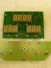
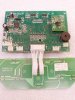
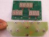
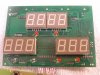
You shouldn't need the LED board at all! Although I have only run this for 4 minutes at a time, I only concentrated on what the LED board sent out, when it wasn't throwing an error. It was consistent, and I tried to account for every situation - start, stop, speed up/down, key removed. Every other feature the LED board has, like change programs etc.. can only effect the speed value sent to the power/motor-board. As this unit didn't have an incline motor, all it can really do is control the motor.

When the 2 packets are sent to set the speed will the controller stay at that speed or does it need a constant feed of identical packets?

It appears to need constant packets, regardless of whether the speed value is changed.

To change speed depending on above answer, would I simply change the binary all at once and allow the motor board to ramp up or down the speed or do I need to change the binary one bit at a time?

Good question. Given that the LED board sends out speed values that are incremented at the start (slow start up), I believe it is down to the control signal to determine the slow start - the motor board just sets the speed to what its told to.
I'm sure it won't change speed 'instantly', but, say if you set it to 4/32, then suddenly 24/32, I don't think it would take long to change speed, maybe a second?

If it really does require the speed to only change by one bit at a time..
Perhaps it sends each one 'twice' for error detection, meaning both speed packets will have the same speed value, and can only change once it sends the next two speed packets. So updating the speed value would happen every 4 packets (two speed, two control), giving a maximum 'change' of speed of 1/32 (assuming a 5-bit speed value) every ~400ms. That would mean if you were to increment the speed as quickly as it wants (1 bit at a time), it would take over 12 seconds to go from 0 to max rpm. Seems far too high to me, so although its a not the best reason to think so... I'm fairly sure the speed value is absolute, and can be changed next packet by any amount - any remaining ramp up/down period would be down to the power board's micro.

One other thing that puzzles me is the timing issues. I have never had much success with interrupts and tend to avoid them if I can. Will I need them or is there a way I can create the packets without them? Maths is not my strong point so any simple way is always best for me. ;) Plus any way you can simplify the method will always benefit others with the same problems.

Yeah I used to avoid interrupts where-ever possible :) But once you start using timers has 'hartbeats' or periodic updating of things, you start to get into the mindset of 'synchronous events', that need to be done in regular intervals, and asynchronous events, that can be done regularly, but with no real urgency. It can get complicated very quickly, but also allows a micro to do a hell of a lot... and react quicker to events.

With a PIC pumping out the signal to the motor, if you don't use interrupts, only fixed delays between output transitions, then your micro will be tied up 'doing stuff' for the entire packet - but even then that's only 60ms, every 100ms. So 60% of the time will be busy. Inefficient, yes, but that still leaves 40ms, every 100ms to read ADC's, a switch, calculate speeds etc.. and on a PIC running at 4MHz, that still gives you 40k instructions :)

If you were to use the PIC to read in serial data, or capture fast events, then interrupts would have to be used. For safety I would use at least one interrupt - the stop button. If the PIC has just started sending one packet, and you hit the stop button, it won't check that button for at least 60ms (whilst its kicking out bits), and even then you need to wait maybe another 20ms to check it wasn't a glitch (button debounce), so already we're approaching a 100ms delay between hitting an emergency stop, and the motor *starting* to stop. Even in that case, 100ms isn't that long.

So, do you need interrupts? naaa. It would be nice! Because the signals output changes every ~ 1.625ms, which on a 4MHz PIC is.. 1625 instructions. Even if the interrupt uses 125 instructions it means you have 1500 to play with *between* bits in the packet. Add on the large gap between packets and you have a situation where your PIC free to do other things 95% of the time, as opposed to 40%.

I would just use timer1 to overflow every 100ms. And in your interrupt, just raise a flag. In your main code you check that flag, if set, you send a packet, then increment a 2 bit counter that determines what 'packet' you send (two speed, two control = 4 packets). After it has sent the packet, it reads the ADC, and checks the status of buttons - and makes the appropriate changes to speed, or start/stop the signal, then clears the timer flag. Then it just loops back, waiting for this flag to be set again (by the timer interrupt). As long as you do your ADC reading, and button checking within 40ms, it'll be fine. The timer just ensures a packet is sent every 100ms.

Its simple, maybe not the most efficient, but it'll work, and you'll read your ADC/buttons every 100ms. If it seems slow to react, you can always knock something more complicated up later (using interrupts).


Can't thank you enough for all the work you put into this project mate. I know its doubtful but if you ever get stuck and I can help I am there like a shot.

Any time sir :)


My chicken dinner awaits!

BT
 
Last edited:
Status
Not open for further replies.

Latest threads

New Articles From Microcontroller Tips

Back
Top