Continue to Site

Welcome to our site!

Electro Tech is an online community (with over 170,000 members) who enjoy talking about and building electronic circuits, projects and gadgets. To participate you need to register. Registration is free. Click here to register now.

  • Welcome to our site! Electro Tech is an online community (with over 170,000 members) who enjoy talking about and building electronic circuits, projects and gadgets. To participate you need to register. Registration is free. Click here to register now.

What is wrong with my transformer output?

Status
Not open for further replies.

sr13579

Member
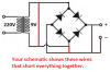
The thing is, I was trying to regulate a 220V-9V to 5 volt. I did it though. Everything was right.I was trying to make a dark sensor with NOT gate
(
)
The settings are good. But it wasn't working fine with the AC to DC adapter.( It is working fine with a battery like the video). The thing is while it is attached with the adapter (AC-DC) the LED is working automatically. Why it is happenning. Is so.ething wrong with my mains connection.Or is there a earthing problem going on.
 
Where is the circuit diagram of how you have the AC to DC connected?
 

Attachments

  • for elwctro tech.jpg
    for elwctro tech.jpg
    488 KB · Views: 256
What is the value of the capacitor?

Are you sure that the bridge rectifier is connected correctly?

JimB
 
Also, what NOT gate are you using?

Show us a complete schematic of how it is connected.
Unised gates in the IC should have inputs connected to 0v or the +ve supply, not left floating and unconnected.

One big error in the video, there is no current limiting resistor for the LED.

JimB
 
In your schematic you completely shorted the transformer output and the bridge rectifier. You show the AC input connected directly to the DC output, also the DC output is shorted.
You also do not show a 5V regulator IC.
Your video does not show a part number for the NOT gate so it might be destroyed by the 9VAC that got to it.
 

Attachments

  • bridge rectifier.png
    bridge rectifier.png
    56.5 KB · Views: 244
Last edited:
In your schematic you completely shorted the transformer output and the bridge rectifier. You show the AC input connected directly to the DC output, also the DC output is shorted.
You also do not show a 5V regulator IC.
Your video does not show a part number for the NOT gate so it might be destroyed by the 9VAC that got to it.
My bad.(I was trying to draw a block diagran)
 
With all due respect. Here is the situation. You ask for help and we are to assume that all the connections have been made correctly. We are asked to answer questions as to why things don't work. How are we to know that all has been wired correctly without seeing what your eyes see? This makes helping very difficult. We are to guess what may be or not be. The thread grows longer than would need be if we had a schematic of HOW HAVE YOU HOOKED THINGS UP? Help us help you by providing enough information to solve the problem. Try your best to answer the questions asked in the forum.
Be prepared to provide a close up photo of present non-working circuit and ALL its components. This would assist in finding possible issues with your problem circuit.
 
What is the part number of the NOT gate?
What is the value of the capacitor?
Where is the 5V regulator IC?
Did you measure the DC supply voltage? Is it about 12VDC?
 
Status
Not open for further replies.

Latest threads

New Articles From Microcontroller Tips

Back
Top