Continue to Site

Welcome to our site!

Electro Tech is an online community (with over 170,000 members) who enjoy talking about and building electronic circuits, projects and gadgets. To participate you need to register. Registration is free. Click here to register now.

  • Welcome to our site! Electro Tech is an online community (with over 170,000 members) who enjoy talking about and building electronic circuits, projects and gadgets. To participate you need to register. Registration is free. Click here to register now.

What happen to the relay????

Status
Not open for further replies.

Gundam82

New Member
hey.... pls help me...

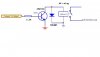
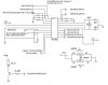
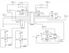
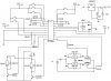
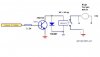
I using a 6 volt relay to operate my DC motor, the signal is from microcontroller.... is rated current is around 2mA.. then i using one transistor 2n2222 to swtch on the relay.. at first it work well. can switch on the relay.. but after i connect the DC motor together with the relay....
when a signal is send from micrcontroller... relay doesn't work anymore..!!! why ya~~~~!!! pls pls pls......urgent.!!!!!!!
 
I'd say the relay did its spiking thing (it does have a technical term) when the contacts closed, and this destroyed either the transistor, the IC, or both.

You should always put a diode across the coil of a relay to stop this happening 8)

HTH,

Tim.
 
Hey...... i tired to add diode (1n4001) between the relay oledi... i works well.. the relay can switch on the dc motor.... but when i but a high torque motor one.... but cannot switch the relay .`~~~ what happen?? any idea???


I using.... diode 1N4001, RELAY 6v, transistor NPN (2N2222), signal from Microcontroller... rated current around 2mA.... !!

PROBLEM>...... when put the normal dc motor.. relay work perfectly... BUT>>> when put the HIGH torque motor... The relay just click one time... then cannot work anymore.~~!!........ i want learn the solution..!!!! :?
 
Another possibility: when the relay switch higher current, generated too much noises, and the micro program go to dead loop or freeze...
 
HEy.~~~~ yayayaya..... smae thing happen like u my case.... when put a high torpue dc motor.... once i send signal from microcontroller to the relay through transistor, my micocontrolle freeze there.... i need to restart the power supply !!!!! wat happen ya????

Using more higer power relay is that means that using 9VDC or 12 VDC relay????
 
This is my connection for the relay...!!!!!

icc... because of the high torwue motor generate too much noises when the relay switch higher current.......... this is why my microcontroller will go to dead loop or freeze.. there..... and i need to turn off and on the power supply.. !!! thanks~~~~


ERm... is there any slolution to sovle this problem??? other than change to more higer power relay???? 9v and 12v?????


i still learning....................~~~~!!! (@_@)
 

Attachments

  • relay1.jpg
    relay1.jpg
    14.7 KB · Views: 723
Gundam82 said:
This is my connection for the relay...!!!!!

icc... because of the high torwue motor generate too much noises when the relay switch higher current.......... this is why my microcontroller will go to dead loop or freeze.. there..... and i need to turn off and on the power supply.. !!! thanks~~~~


ERm... is there any slolution to sovle this problem??? other than change to more higer power relay???? 9v and 12v?????


i still learning....................~~~~!!! (@_@)

Try putting some filtering on +5V right at the microcontroller. Put low ESR capactiance (like maybe 1-33uF electrolytic) and 10,000 pf ceramic right at the 5V pin on the micro. You could also put a zener diode 5.1V on +5V supply. This might help with the spike causing micro to freeze/reset.

With that said, the real issue is likely rooted in your layout. Some ways are better than others when high current devices like high torque motors are used. Can you post a picture of how its all connected?
 
As I suggested above, post the circuit! - all of it, the driver transistor part isn't any help - it gives no idea of what your power supply connections are, nor what decoupling capacitors you have fitted. Show the motor connections as well!.
 
thanks for ur suggestion... but i still not clear how is the conneciton for the capacitor?? to which +5 supply~~~ below is my circuit to control the motor using relay~~~!!!!!
for the motor part i didn;t put any capacitor o wat... just as shown above the relay connection..... !!!! i have no idea at all .... when use high torque motor... the PIC will deep loop....!!but i refer to other's people connection.... they all also the same..!!! how ya??
 

Attachments

  • circuit_198.jpg
    circuit_198.jpg
    38.9 KB · Views: 678
That's more like a block diagram that a circuit diagram!, I'm presuming there's a lot of parts that you're not showing?.

We need to see the exact circuit, as you have it connected, including the power supply, and all decoupling capacitors - everything!.

As you show the motor being fed from +5V, I'm presuming that you are using the same supply as the PIC?.

If your power supply uses a 7805 regulator, as soon as the motor turns ON it's liable to draw more than the 1 amp maximum the regulator will provide - so the +5V rail will fall drastically, the PIC will reset, and the motor will stop again. It's advisable to feed any heavy current devices from a different supply to the micro.

This is why we need the FULL circuit, instead of just guessing!.
 
here is my circuit.... i hope that can make everyone more clearing.... erm... i using 78L05 as my Vcc .. supply... yup..motor supply is separately...!!! is it possibly i connect the smae suppply to all the motor together???........... i didn;t use any capacitor in my this circuit..... as shown .... thanks~~!!!!! :roll:
 
what are the specs of the relay, as well as the voltage and current consumption of the motor you are driving?

seems the circuit is right for me. but try putting an NTC thermistor capable of holding the current consumption of your motor (lets say motor eats 3A, put an NTC thermistor that can handle 3A to 10A just for an example) in series with the controller load, which is the motor.
 
but try putting an NTC thermistor capable of holding the current consumption of your motor (lets say motor eats 3A, put an NTC thermistor that can handle 3A to 10A just for an example) in series with the controller load, which is the motor.


sorry~~~ this is my circuit....... wat uis NTC thermistor?? how about if i use 9v relay?? like soneone suggected above??? is it possible to solve the problem ????
 

Attachments

  • untitled_695.jpg
    untitled_695.jpg
    41.2 KB · Views: 618
You're now showing four different supplies, but with no suggestion of where they come from? - are they four totally seperate batteries?. Also, you're still not showing the 5V regulator, so we've no idea what interaction might exist between the 5V supply and the other supplies, or if you've fitted the essential capacitors close to the 78L05?.
 
Okok... erm.... i using 3 separate supply... all the Vcc is from voltage regulator 7805.... and V2 is 12v for both and V3 is 9V for another part... total 3 supply... i didn;t put any capacitor at there except for the voltage regulator.......... is that ok?? erm... shoule i put any capacitor at the supply of the 12V and 9V?? hope this will make sir clear.. about the information....... :wink:


learn and learn........!!!!!
 

Attachments

  • untitled1_102.jpg
    untitled1_102.jpg
    42.2 KB · Views: 406
Gundam82 said:
Okok... erm.... i using 3 separate supply... all the Vcc is from voltage regulator 7805.... and V2 is 12v for both and V3 is 9V for another part... total 3 supply... i didn;t put any capacitor at there except for the voltage regulator.......... is that ok?? erm... shoule i put any capacitor at the supply of the 12V and 9V?? hope this will make sir clear.. about the information

You certainly need some capacitors about, for a start the spec for the 7805 requires capacitors as close as possible to the input and output pins, you show capacitors on the output, but not the input. I would suggest a good size electrolytic (470-1000uF) on the input side, as well as a 100nF close to the pin of the 7805. I would suggest you also add similar large capacitors on the other supplies.

I would also suggest you mount capacitors as near as possible to the PIC supply pins, a 100nF or a 1uF would be suitable (a 1uF electrolytic may well be smaller than a 1oonF).

You say you have three supplies?, what feeds the 7805?, is it the same 9V that feeds the motor? (in which case you've only got two supplies) - that could be a prime reason for your problem?. Are you using three totally seperate batteries?.
 
YEAHHHHHHHHHHHHHHH.... i solve the probelm oledi........thanks everyone.............. because u all give me suggestion and wat is the problem ...!!!!!! i tried to solve.. it...... finally.... its work perfectly...!!!!
under using high torque motor.........!!!!!!


Soluiton...at first i put filtering at supply , across relay.. all cannot...still the same thing happen ....then i tried to put capacitor acrosss to the motor's leg..... as shown the circuit !!!!!! i put 100uF.... .... its work....!!
erm..... how can i determine wat value of the capacitor value should i put?????
 

Attachments

  • relay1_972.jpg
    relay1_972.jpg
    17.3 KB · Views: 408
erm.. ic... okok... i will try to use urs suggestion..... thanks ya... u helped me a lot.... act... if can reduce the power supply sure better... wat i worry is... if i combine the supply....!!!!

1. worry it wil damage my PIC.... maybe becos of the feeback o wat...
2. worry if combine the supply to alll the motor.... maybe the performace will affected becos maybe a motor will carry more current than another... is it occur?? i just guess.....


any suggestion???? thanks . alot (@_@)


Learn and learn.................... keep it...
 
Status
Not open for further replies.

Latest threads

New Articles From Microcontroller Tips

Back
Top