Continue to Site

Welcome to our site!

Electro Tech is an online community (with over 170,000 members) who enjoy talking about and building electronic circuits, projects and gadgets. To participate you need to register. Registration is free. Click here to register now.

  • Welcome to our site! Electro Tech is an online community (with over 170,000 members) who enjoy talking about and building electronic circuits, projects and gadgets. To participate you need to register. Registration is free. Click here to register now.

Variable voltage monitor help

Status
Not open for further replies.

shahh

New Member
Help,
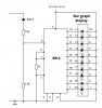
I am trying to build a variable voltage monitor using LM3914, and 10 leds. This circuit could be hooked up to ANY battery (9, 12, 24, or 48 volts), and should work w/out changing the values of resistors. For eg. if i hook up a 24V battery, it should display ~18V for the lowest to ~26V for the highest.


Thank you
HS
 
variable voltage monitor circuit

How would i build this circuit by switching from a 9v to 12v to 24v battery, with less to no modifications.
 
Re: variable voltage monitor circuit

shahh said:
How would i build this circuit by switching from a 9v to 12v to 24v battery, with less to no modifications.

It depends exactly what you want to do, if you want an 'expanded scale' reading - as you would use in a car, reading 9V to 15V you need to subtract the initial 9V.

A simple (and crude) way to do this is with a zener diode - feeding the meter through a 9.1V zener diode will remove about 9V.

What exactly are you wanting to do?.
 
variable voltage monitor circuit

this is what i'm trying to do:
Lets say i want to measure a 24V battery, and the range of voltage monitored on the leds is 26V-18V=8V. The 10 led bar graph should display the voltage in .8V increments. This same circuit should work for any variable voltage supply. I need help building this circuit.

Thanks.
 
Definitely need switching the voltage divider on input to keep the same resolution...
Possible also automatically with comparators ( auto ranging)
 
variable voltage monitor circuit

Hello guys!

switching the voltage divider resistors? I understand that but how would that help me measure the variable voltage coming in. The voltage dividers are there just to half the incoming voltage to the LM3914. I guess i need a example of some sort.

HS
 
shahh,

There is no possible way for any circuit to know if it is connected to a good 9V or a really bad 12V battery!
The only way is to manually switch the circuit before connecting the battery.

Ante :roll:
 
variable voltage monitor circuit

that kind of answers my questions, but is it possible to build a voltage monitor where you can adjust the voltage range to be displayed on the led. For eg. using a 24V battery, I want to display ~18V for lower limit to ~26V for upper limit. So the range would be 26V-18V=8V. Any idea on how i can build that kind of circuit using LM3914.
 
shahh,

Maybe this will help:

Ante :roll:
 

Attachments

  • bargraph.gif
    bargraph.gif
    10.8 KB · Views: 1,290
variable voltage monitor circuit

Thanks for the circuit, few questions:

-Since this is connected to a 36V battery, what VOLTAGE RANGE will be displayed on the leds, keeping in mind if using a fully charged battery.
-Next will this circuit work for a 12,24,and 48V battery. Will i have to adjust the voltage dividers only?

Thanks.
 
If I remember correctly LM3914 has input range (pin 5) 0-5VDC.
Divider 22k/1.5k would expand this to ca. 0-80V. With ca 20V dropped
on Zener diodes, range would shift from 0-80V to 20-100V.
So LEDs would turn on 28, 36, 44, 52, 60, 68,76, 84, 92 and 100V.
At 100V at the input zener diodes and 1k/1W will be overloaded.
For example at 80V drop on 1k, resistor would have to have to
sweat ca 6.4Watt and with only 1W rating it would certainly smoke...
If you get rid of zeners and 1W resistor and change 22k/1.5k divider
to 22k/2.2k for example, you would get linear scale 0-50V with LEDs
turning on 5, 10, 15, 20, 25, 30, 35, 40, 45 and 50V.
For more detail get the datasheet and read it. you will also find sample circuits.
 
variable voltage moinitor

the question is what voltage range will be displayed by using a fully charged 24V battery. I would like it to display ~10V for lower limit and ~28V for the upper limit. Is it possble to increase/decrease this range?

Thanks.
 
variable voltage monitor circuit

the question is what voltage range will be displayed by using a fully charged 24V battery. I would like it to display ~10V for lower limit and ~28V for the upper limit. Is it possble to increase/decrease this range?

Heeraj
 
shahh,

Here is a different approach to measuring battery voltage.

Ante :roll:
 

Attachments

  • lead_acid_bat-meter.pdf
    77.2 KB · Views: 647
shahh

I guess you did not read the datasheet...
You have to start by defining input range.
For example you wanted to have input range 10-28V.
Since you have 10 LEDs, this range would be divided
into 10 equal steps.

28-10=18V for full range which makes steps
1.8V each (1.8, 3.6, etc.) but they will start
from 10V so the first LED would turn on 10+1.8=11.8V.
Thats not what you wanted so we have to change the lower
range limit down by ca 2volts making operating range
8-28V. This makes 20V span which means that each step
would be 20/10=2V which makes LEDs turn on following
voltages:
8+2=10
8+4=12
8+6=14
8+8=16 etc.
Where 8 is beginning of our range (8-28V).

So when you bring input signal of 10V, first LED would
turn on. This 8V shift is created by zener diode such
as 8.2V.

Scaling:
When you bring 10V, zener will take 8V (or 8.2)
and the voltage divider set from two resistors (or
potentiometer) would get the remaining 2V (10-8=2).
When you bring 28V, zener will take 8V (or 8.2)
and the voltage divider set from two resistors (or
potentiometer) would get the remaining 20 (28-8=20).
So the voltage divider is working with span of 0-20V.
Input of the LM3914 is 0-5V (maybe not, check the datasheet)
Which means that we have to divide input signal 4 times
(20V/5V=4) in order to cover full span.

Power dissipation on resistor connected to 20V is
P=20*20/R so if you want to use ca 1/4W resistor
this becomes 1/4=400/R or R=4*400=1600 Ohm.
If you choose lower value, this resistor will smoke.
But we are not putting one, we use two of them as
4:1 voltage divider. 1600/4=400 Ohm (lower of the two)
the remaining 1600-400=1200Ohm is the upper of the
two resistors in the voltage divider. Now the value
of 400 is not easy to find but the 390 Ohm is close enough.
You can increase value of both resistors (power dissipation
will go down) but you have to maintain same ratio.
In our case 1200/400 is 3:1 ratio. So if you chose
one of the resistors to be 1k, other should be 3k or
combination of 2.7k and 270Ohm to get as close as possible
2700+270=2970 which is close enough to 3000).
If we go for even higher values, 3.3k and 10k seam to
be reasonably close.

So at the full input voltage of 28V current through
resistors would be only I=(28-8.2)/(3300+10000)=1.49mA
That means power dissipation of the
zener is 8.2V*1.49mA=12.2mW or 0.012W
10k resistor is 15V*1.49mA=22.35mW or 0.022W
3.3k resistor is 5V*1.49mA=7.45mW.
This is what you should be able to do by reading the
datasheet. It's for one range so if you want to calculate
another, just follow the same easy steps (it's just the
very basic math using Ohms Law).
 

Attachments

  • lm3914.jpg
    lm3914.jpg
    22.8 KB · Views: 3,078
variable voltage moinitor

Ante, you last post for the download did not come thru. Can you please post it again.
 
shahh,

Have you tried to right click on (Download) and chose “save as”?
It works for me.

Ante :roll:
 
LED voltage monitor

hi,

check this out. i have used this to monitor voltage main by using a 9v wall transformer to drive the quad op-amp. LM324. you can email me for any question about this.
 

Attachments

  • flashing_voltage_monitor.doc
    38.5 KB · Views: 287
Status
Not open for further replies.

Latest threads

Back
Top