cadstarsucks said:
Briefly if you are on 115V:
230V.
the mains normal operating point is 100-130V
220V to 250V.
the transformer is probably 15%
I don't know what the regulation is but it's certainly better than that, it's an 80VA toroidal transformer and these give pretty good regulation, about twice as good as an E-core transformer so let's say 7.5%. Anyway isn't the voltage of a transformer specified at the full load?
the mains peak voltage is RMSx1.414 or 141-184V
About 311V to 354V but what difference it makes is beyond me, I normally use the output voltage to calculate ripple.
The safe transformer current is rating/1.8 or 1.48A
It's rated for 2.67A, but I disagree, I want to be able to draw at least 1.5A so the transformer needs to be rated for at least [latex]1.5 \times sqrt{2} = 2.21A[/latex].
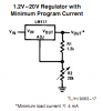
The regulators need 3V to operate - so you need 18 volts at the valley of the filtered waveform, or preferably an 18V transformer
You're mistaken, providing it's not too hot or not too cold the LM217 has a dropout voltage of
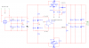
[email protected] so minimum DC voltage needs to be 17.25V,therefore a 15V transformer will do, let's calculate the ripple assuming a 4700µF capacitor.
[latex]V_{RIPPLE} = \frac{I_{LOAD}}{2FC}= \frac{1.5A}{2 \times 50 \times 4700 \times 10^{-6}} = 3.2V[/latex]
The peak voltage is [latex]15 \times \sqrt{2}= 21.2V[/latex]
The minimum voltage in-between the ripple is [latex]21.2 - 3.2 - 0.7 = 17.3V[/latex]
The diodes need to be rated for 2A or better
They only conduct for half the cycle so they only need to be rated for 1.11A, either way I've used a 3A 400V bridge from an old PC power supply so it doesn't matter.
and the caps should have a 4.5A RMS rating...
Why?
Sure, the peak current might be 4.5A but the RMS current is probably nearer to I/√2.
That is what is supposed to be done. For a complete discussion see the end of this catalog and cut corners as you like:
**broken link removed**
I dissagree with some of the formulae and figures.
For a start the formula for the capacitor is incorrect if you use a linear regulator, it says "2000µF/amp for 3V p-p ripple", this assumes a resistive load rather than a constant current load. A 2000µF capacitor will give 4.167V of ripple @60Hz when given a 1A constant current load. The formula used in my calculation above if pretty accurate for constant current loads, try simulating it in a SPICE simulator.
The claim that rectifiers can't handle surges and need to be rated to the full output current is rubbish, a 1N4001 rectifier can withstand a non repetitive peak surge of 30A and the WOO5 can take 50A for a 8.3ms half sine wave (this is just a ballpark figure I didn't use 1N4001s or a WOO5 in my design). I might see the point if this was a huge power supply but not in my little power supply where the internal impedance of the transformer will limit the surge current to a safe level.
The only corner I have cut is undersizing the filter capacitors slightly so I might see some ripple on the output if the mains voltage is a little too low, the regulator is too hot/cold, the capacitors are in the lowest tolerance band, or the voltage is whacked up to 15.7V (15V is the design maximum but due to component tolerances it can go 0.7V higher). I know I should've used 6800µF capacitors but I didn't have any handy, for a start as the transformer is slightly over-sized the output voltage will be higher than expected at full load, 1A is good enough for most applications and I'm not doing this professionally, besides there's nothing stopping me piggy backing a couple of 2200µF capacitors on there.
I prefer offline switchers myself but most people do not have the resources that I do.
I prefer switchers too, but they can be too noisy and troublesome to build.
") Good luck, I hope you worked it out.
Good luck, I hope you worked it out.
 hm: impedance you could have some high instantaneous currents. But the 3A bridge will probably not be a problem. The thing is a cap is not a resistive load and there is only one ohm between it and an ideal AC source.