jrz126
Active Member
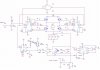
I just built a high power H-Bridge for my inverted pendulum project and I thought I would share it.
I was running it at 45VDC into a 12 ohm, 200W resistor with no problems (thats over 150W). I was alittle over ambitious with this H-Bridge, it turns out my servo motor for the pendulum draws <50W when running. The motor itself is capable of 200W.
There's a few things that need to be noted:
1. High voltage is lethal. attempt at your own risk.
2. This circuit generates alot of electrical noise. Opto-isolation of all logic inputs is definitly recommended. Add additional stiffening/bypass capacitors across all voltage supplies.
I'm thinking about making up a PCB for this circuit over winter break. I'll be sure to post it if I do.