Hero999
Banned
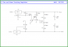
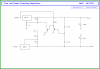
They don't try to keep the voltage at zeroNo, the feedback path is via the 1.18K and 1.2K divider. The transistors, combined with the LM317, try to keep the voltage at the junction of the divider at zero.
It doesn't hold it at 0V but at -Vbe, 700mV nominal.
I haven't simulated yet, I don't have all the models.
Here's a part calculation, part guess of what the voltages and currents should be around the circuit.
")