Continue to Site

Welcome to our site!

Electro Tech is an online community (with over 170,000 members) who enjoy talking about and building electronic circuits, projects and gadgets. To participate you need to register. Registration is free. Click here to register now.

  • Welcome to our site! Electro Tech is an online community (with over 170,000 members) who enjoy talking about and building electronic circuits, projects and gadgets. To participate you need to register. Registration is free. Click here to register now.

Variable Bipolar Power Supply

Status
Not open for further replies.
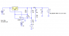
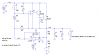
The role of the opamp here is to provide a steady voltage for the LM337 adj pin so that LM337 would function normally as a voltage regulator, and not to "regulate" the LM337 to cause it to react to output voltage transience. It is in effect a replacement of a variable resistor for setting the output voltage. Opamp speed is never an issue.

The worst thing to happen is the opamp output voltage varies or being modulated due to load variation. Use every filter that you can find to make the opamp inmute to input voltage transience. Slow opamp like 741 works best.
 
eng1 said:
I don't think so. It is compensated for unit gain, like the ua741.
So it is, I didn't bother to read the datasheet!


The LM337 has a local feed-back (the 120 ohm resistor) and it keeps the constant voltage accross the adj pin and the out pin, as we said. With this configuration it does no react to transients as it does when the adj pin is grounded. I mean.. if the output of the op amp were a sine wave, the output of the LM337 would be a sine wave + 1.25 V
Of course it still reacts to transients when the adj terminal is grounded. Try setting the output to 1.25V and then varying the load, it still regulates fine.


If you use the op amp around the LM317 you can use a 220 ohm resistor (instead of 120 ohm) and the current will be 1.25/220 = 5.7 mA
But why would I want to?

The reason for using a 220ohm resistor was purely due to get the correct ratio as I only have a 2k5 10-turn pot available. Putting it on the negitive supply wasn't an option since the minimum load is 10mA and I don't have a 1k125 pot!

eblc1388,
You've put it far better than I have. I was beggining to think I was incorrect when I'm right. The regulator is doing the regulation not the op-amp! The adj pin needs to to be held at a fixed voltage and the LM337 handles the load variations.
 
Hero999 said:
The regulator is doing the regulation not the op-amp!
I totally agree with you.

When I talked about "transients", I was thinking of variations between the positive and negative outputs (tracking).
We want a constant output and this is handled by the regulator; another aspect is tracking and this is handled by the op amp.

I will check this thread and I look forward to view the pictures and read any news about this circuit.

Regards
 
I'm glad we now agree but I'm more interested in why your circuit didn't work and mine does. I'm sorry I didn't understand you, what was the problem? Did it oscillate? Perhapps Ron had a point about phase shift and stability. Just because the LM337 doesn't contribute any gain it doesn't mean it doesn't cause any phase shift.

I think you could try adding a lowpass filter or a slower op-amp like the uA741.
 
Hero999 said:
I'm glad we now agree but I'm more interested in why your circuit didn't work and mine does. I'm sorry I didn't understand you, what was the problem? Did it oscillate? Perhapps Ron had a point about phase shift and stability. Just because the LM337 doesn't contribute any gain it doesn't mean it doesn't cause any phase shift.

I think you could try adding a lowpass filter or a slower op-amp like the uA741.
I can't find an LM337 spice model, but an LM317 in a similar circuit behaves as below (keep in mind this is a sim, not hardware). I ran the sim with compensation cap values of 0 and 100nF. The load current is pulsing between 10mA and 100mA, as shown on the schematic. The 0.1 ohm resistor in series with the 10uF cap is ESR. I tried 0.01 ohms, and it still oscillated.
The diode on the output in my schematic keeps the current load from pulling the output several kV negative in the sim.

Have a look at the National LM337 datasheet's equivalent circuit. I think you'll see this is not much like a PNP emitter follower. It has loads of loop gain and an RC frequency compensation network.
 

Attachments

  • FB reg stability waves.PNG
    FB reg stability waves.PNG
    26.3 KB · Views: 595
  • FB reg stability sch.PNG
    FB reg stability sch.PNG
    10.4 KB · Views: 734
Hi Ron,

How about adding a 10uF capacitor from junction of R1 & R3 to 0V?

Can you post also the .asc file (I'm too lazy to redraw the circuit in Switchcad)?
 
eblc1388 said:
Hi Ron,

How about adding a 10uF capacitor from junction of R1 & R3 to 0V?

Can you post also the .asc file (I'm too lazy to redraw the circuit in Switchcad)?
Here are (hopefully) all the files needed. Try the 10uF at the summing node. It causes some VERY low-level underdamped ringing. Not bad.
 

Attachments

  • fb stability.zip
    3.1 KB · Views: 491
Thanks Ron. The simulation is working.

I have increased the value of the additional cap to 100uF but without the frequency compensating capacitor Cc and the output trace is now as good as your previous circuit with the value of Cc compensating capacitor = 100nF.
 
eblc1388 said:
Thanks Ron. The simulation is working.

I have increased the value of the additional cap to 100uF but without the frequency compensating capacitor Cc and the output trace is now as good as your previous circuit with the value of Cc compensating capacitor = 100nF.
That's good to know as an intellectual exercise, but it obviously is not as space- or cost-effective.
 
I wonder why circuit worked so well then?

Perhapps it isn't working that well as I haven't looked at the output on a scope and my multimeter was just taking the average output.

I'm intrested about how the LM337 adds gain to the system. Whilst I'm aware it isn't just a PNP transistor, I was under the impression that it is in a situation similar to a common emitter amplifier with full negitive feedback. Suppose you increase Vadj with respect to 0V, Vload responds to keep Vadj with respect to Vload at 1.25, just like increasing Vb increases Vload to keep Veb at about 0.7V on a common emitter amplifier. Can you see my point?

I don't understand why in your simulation the load isn't acting as negitive feedback in the LM317 circuit like I'd expect.
 
Hero999 said:
I'm intrested about how the LM337 adds gain to the system.

This is a functional diagram of a LM317. You can obtain the one for the LM337 with simple changes.
We're used to see two resistors (R2, R1) that form a feed-back network and set the output voltage.
If we don't use the standard configuration and we add an op amp the circuit is more complicated, especially as far as the loop gain is concerned.
 

Attachments

  • pos_adj_reg.png
    pos_adj_reg.png
    7.7 KB · Views: 681
Last edited:
eng1 said:
This is a functional diagram of a LM317. You can obtain the one for the LM337 with simple changes.
We're used to see two resistors (R2, R1) that form a feed-back network and set the output voltage.
If we don't use the standard configuration and we add an op amp the circuit is more complicated, especially as far as the loop gain is concerned.
But can you think of a way to make dual tracking regulators without using a scheme similar to the one we have been talking about?
 
Adjustable Symmetrical Power Supply
 

Attachments

  • ~$justable Symmetrical Power Supply1.doc
    162 bytes · Views: 785
My computer wants me to guess what version of Word (or whatever) you used. At 162 bytes, I can't imagine it is a schematic. Is it? How about posting it as a GIF or PNG?
 
Ron H said:
But can you think of a way to make dual tracking regulators without using a scheme similar to the one we have been talking about?

Yes. You can use a voltage reference and a dual op amp. The first section amplifies the ref. voltage with a variable gain (non-inverting). Its output is inverted by the second amp (gain = -1, with 1% resistors).
These equals voltages (with opposite polarities) are connected to the adj pins. Resistors between output and adj pin of each regulator are still necessary (you made me aware of this some time ago) but they don't set the Vadj; they only set a minimum load current for the regulators (1.25/R).
The op amps are used in a closed loop configuration. If they add a pole, it is beyond the unity gain frequency of the regulators and doesn't affect stability. The LF411/2 have low offset, low drift, high bandwith, high output current.
The positive output can track the negative one with good precision in my opinion. The error is mainly the mismatch between the internal references of the regulators, but this could be be easily eliminated because it is constant.
 
Ron H said:
My computer wants me to guess what version of Word (or whatever) you used. At 162 bytes, I can't imagine it is a schematic. Is it? How about posting it as a GIF or PNG?

sorry sir for inconvenience here's the files in png and gif.
 

Attachments

  • adjustable symmetrical power supply.png
    adjustable symmetrical power supply.png
    32.8 KB · Views: 868
  • part list.GIF
    part list.GIF
    27.9 KB · Views: 559
Most of the dual pots I've seen have tracking specs around 20%. I've never actually tried to build supplies with them, but I do have an op amp version. I have an old plugboard which had built-in +5, +15, and -15 volt supplies. I modified the ±15 supplies by changing the trimpot on one to a pot with a knob on it, then added the op amp to make them track.
A dual pot costs more than an op amp, the op amp version has better tracking with good stability.
 
Last edited:
eng1 said:
This is a functional diagram of a LM317. You can obtain the one for the LM337 with simple changes.
We're used to see two resistors (R2, R1) that form a feed-back network and set the output voltage.
If we don't use the standard configuration and we add an op amp the circuit is more complicated, especially as far as the loop gain is concerned.
I have looked at the internal diagram and I appreciate that is has some gain and phase shift. What I don't get is why the load doesn't cause negitive feedback and cancel the change at Vadj. I visualise this as being a unity gain stage in the feedback loop of a very large gain stage.

I've tried simulating this myself. I didn't have a model for the LM317 so I've made one using a uA741 with a few other componants and it works. However Ron's model will be far more acurate than mine so I accept his results over mine.

The only thing I can think of is I'm probably wrong. Maybe the LM317 acts as an open loop gain stage which is sure to cause oscillation. Perhapps the uA741 is over- compensated to such a high degree that it cancels this effect out so my circuit works as does my simulation.
 
Here's the simulation of my model of the LM317. Is is acurate enough for this? The only thing that's missing is the current and thermal overload protection circuits.

I couldn't upload this for some reason so I've uploaded it somewhere else.
**broken link removed**
 
Hero999 said:
Here's the simulation of my model of the LM317. Is is acurate enough for this? The only thing that's missing is the current and thermal overload protection circuits.

I couldn't upload this for some reason so I've uploaded it somewhere else.
**broken link removed**
With the 741's common mode input level at zero volts, you need a negative supply for it.
Try a pulsed current sink for the load. I ran basically this same sim. See below.
First waveform, Ccomp=0.
Second waveform, Ccomp=100nF.
 

Attachments

  • LM317 equiv with op amp feedback sch.PNG
    LM317 equiv with op amp feedback sch.PNG
    23.9 KB · Views: 573
  • uncomp.PNG
    uncomp.PNG
    27.9 KB · Views: 408
  • comp with 100nF.PNG
    comp with 100nF.PNG
    11.4 KB · Views: 425
Status
Not open for further replies.

New Articles From Microcontroller Tips

Back
Top