// Swordfish BASIC sixteen channel software PWM using TMR2 and 3 pot ADC inputs
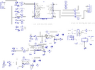
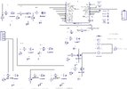
// schematic https://www.electro-tech-online.com/threads/using-pwm-to-dim-led-neon-strip.165067 post #112
// v3 - programmable outputs with Drink and Straw animation
device = 18F2221
clock = 32
include "intosc.bas"
// do NOT include setdigitalio
// to use PORTB for the ADC all pins must be in analog mode due to the way
// these old pics map ADC inputs
include "adc.bas"
// ADC pot inputs
// used to set the PWM duty cycle for PWM1-PWM8 and LED1-LED8
// connect pot upper lug = VDD, lower lug = GND, wiper = port IO
dim
POT1 as PORTB.0, // RB0/AN12
POT2 as PORTB.1, // RB1/AN10
POT3 as PORTB.2 // RB2/AN8
// ADC channels
const
CH_POT1 = 12, // AN12
CH_POT2 = 10, // AN10
CH_POT3 = 8 // AN8
// PWM outputs (controlled by POT1 and POT2)
dim
PWM1 as PORTA.0, // controlled by POT1
PWM2 as PORTA.1,
PWM3 as PORTA.2,
PWM4 as PORTA.3,
PWM5 as PORTA.4,
PWM6 as PORTA.5,
PWM7 as PORTA.6, // controlled by POT2
PWM8 as PORTA.7 // controlled by POT2
// LED PWM outputs (all controlled by POT3)
dim
LED1 as PORTC.0,
LED2 as PORTC.1,
LED3 as PORTC.2,
LED4 as PORTC.3,
LED5 as PORTC.4,
LED6 as PORTC.5,
LED7 as PORTC.6,
LED8 as PORTC.7
// this structure holds the on-off state of the pwm and led outputs
// to turn an output on, set it to 1 (ie 'vPORTS.vPWM2 = 1')
// to turn an output off, set it to 0 (ie 'vPORTS.vPWM2 = 0')
// dimming for all outputs is still controlled by the pots
structure vPORT_t
vPWM as byte
vLED as byte
vPWM1 as vPWM.bits(0) // PWM1-PWM8 settings
vPWM2 as vPWM.bits(1)
vPWM3 as vPWM.bits(2)
vPWM4 as vPWM.bits(3)
vPWM5 as vPWM.bits(4)
vPWM6 as vPWM.bits(5)
vPWM7 as vPWM.bits(6)
vPWM8 as vPWM.bits(7)
vLED1 as vLED.bits(0) // LED1-LED8 settings
vLED2 as vLED.bits(1)
vLED3 as vLED.bits(2)
vLED4 as vLED.bits(3)
vLED5 as vLED.bits(4)
vLED6 as vLED.bits(5)
vLED7 as vLED.bits(6)
vLED8 as vLED.bits(7)
end structure
dim vPORTS as vPORT_t
// Drink and Straw alias names for PWMx and LEDx states
dim
drink_0 as vPORTS.vPWM1, // PORTA.0-PORTA.5
drink_1 as vPORTS.vPWM2,
drink_2 as vPORTS.vPWM3,
drink_3 as vPORTS.vPWM4,
drink_4 as vPORTS.vPWM5,
drink_5 as vPORTS.vPWM6
dim
straw_0 as vPORTS.vLED1, // PORTC.0-PORTC.5
straw_1 as vPORTS.vLED2,
straw_2 as vPORTS.vLED3,
straw_3 as vPORTS.vLED4,
straw_4 as vPORTS.vLED5,
straw_5 as vPORTS.vLED6
dim drink_no as byte,
straw_no as byte
// pwm duty cycles (from ADC) 0=min, 255=max
dim
pwm1_duty as byte,
pwm2_duty as byte,
pwm3_duty as byte
dim pwm_period as byte
// pwm timer TMR2
dim
TMR2IF as PIR1.bits(1),
TMR2IE as PIE1.bits(1),
TMR2ON as T2CON.bits(2)
// macro to toggle an individual bit
macro toggle_bit(x)
if (x = 1) then
x = 0
else
x = 1
endif
end macro
// set IO pin directions and initial settings
sub InitIO()
// set inputs
input(POT1)
input(POT2)
input(POT3)
// set outputs (low to start)
low(PWM1)
low(PWM2)
low(PWM3)
low(PWM4)
low(PWM5)
low(PWM6)
low(PWM7)
low(PWM8)
low(LED1)
low(LED2)
low(LED3)
low(LED4)
low(LED5)
low(LED6)
low(LED7)
low(LED8)
// set all the variable states to low (off)
clear(vPORTS)
end sub
// pwm TMR2 interrupt
interrupt tmr2_isr()
TMR2IF = 0
pwm_period = pwm_period + 1
// outputs controlled by POT1
if (pwm_period >= pwm1_duty) then // set outputs off
PWM1 = 0
PWM2 = 0
PWM3 = 0
PWM4 = 0
PWM5 = 0
PWM6 = 0
else // set outputs to current variable setting
PWM1 = vPORTS.vPWM1
PWM2 = vPORTS.vPWM2
PWM3 = vPORTS.vPWM3
PWM4 = vPORTS.vPWM4
PWM5 = vPORTS.vPWM5
PWM6 = vPORTS.vPWM6
endif
// outputs controlled by POT2
if (pwm_period >= pwm2_duty) then // set outputs off
PWM7 = 0
PWM8 = 0
else // set outputs to current variable setting
PWM7 = vPORTS.vPWM7
PWM8 = vPORTS.vPWM8
endif
// outputs controlled by POT3
if (pwm_period >= pwm3_duty) then // set outputs off
LED1 = 0
LED2 = 0
LED3 = 0
LED4 = 0
LED5 = 0
LED6 = 0
LED7 = 0
LED8 = 0
else // set outputs to current variable setting
LED1 = vPORTS.vLED1
LED2 = vPORTS.vLED2
LED3 = vPORTS.vLED3
LED4 = vPORTS.vLED4
LED5 = vPORTS.vLED5
LED6 = vPORTS.vLED6
LED7 = vPORTS.vLED7
LED8 = vPORTS.vLED8
endif
end interrupt
main:
InitIO()
// ADC setup
ADCON1 = $00 // all pins set to analog mode, VREF = VDD/GND
ADCON2 = ADC.FRC // ADC clock = Frc
ADC.ADFM = 0 // left justify (we only use the 8 MSB's)
ADC.SetAcqTime(100) // 100us delay
pwm_period = 0
pwm1_duty = 0
pwm2_duty = 0
pwm3_duty = 0
// setup pwm timer TMR2
// 25KHz = 40us/bit -> 40us x 256 = 10240us period, ~10ms period (100Hz)
T2CON = %00000001 // T2OUTPS<3:0>=%000 (1:1), TMR2ON=0, T2CKPS<1:0>=%01 (1:4)
PR2 = 176
TMR2 = 0
TMR2IF = 0
TMR2IE = 1
TMR2ON = 1
// start pwm dimming
enable(tmr2_isr)
drink_no = 0
straw_no = 0
while (true)
// read pots and set pwm duty cycle
pwm1_duty = ADC.Read(CH_POT1) >> 8
pwm2_duty = ADC.Read(CH_POT2) >> 8
pwm3_duty = ADC.Read(CH_POT3) >> 8
// simulate glass being filled
select(drink_no)
case 0: drink_0 = 1
case 1: drink_1 = 1
case 2: drink_2 = 1
case 3: drink_3 = 1
case 4: drink_4 = 1
case 5: drink_5 = 1
end select
if (drink_no < 5) then
drink_no = drink_no + 1
delayms(1000)
endif
// simulate liquid going up straw and emptying the glass
if (drink_no = 5) then
select(straw_no)
case 0: straw_0 = 1
drink_5 = 0
case 1: straw_1 = 1
drink_4 = 0
case 2: straw_2 = 1
drink_3 = 0
case 3: straw_3 = 1
drink_2 = 0
case 4: straw_4 = 1
drink_1 = 0
case 5: straw_5 = 1
drink_0 = 0
case 6: straw_0 = 0 // now empty the straw
case 7: straw_1 = 0
case 8: straw_2 = 0
case 9: straw_3 = 0
case 10:straw_4 = 0
case 11:straw_5 = 0
end select
if (straw_no < 12) then
straw_no = straw_no + 1
delayms(500)
else // start over
drink_no = 0
straw_no = 0
delayms(500)
endif
endif
end while