Continue to Site

Welcome to our site!

Electro Tech is an online community (with over 170,000 members) who enjoy talking about and building electronic circuits, projects and gadgets. To participate you need to register. Registration is free. Click here to register now.

  • Welcome to our site! Electro Tech is an online community (with over 170,000 members) who enjoy talking about and building electronic circuits, projects and gadgets. To participate you need to register. Registration is free. Click here to register now.

using PWM to dim LED NEON STRIP

MrDEB

Well-Known Member
couldn't locate this thread but here is the issue
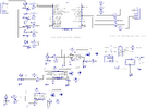
I breadboarded this circuit and it seems to work driving just an LED but I am driving a 12v led neon strip.
The circuit flashes the strip slowly to fast as per pot adjustment.
The 555 circuit works as planned with one LED (it is supposed to change the duty cycle
Thinking the two different supply voltages has something but what to do? Any suggestions?
NOTE THE 7555 IS POWERED BY THE pic
the MOSFET is logic level
 

Attachments

  • dimming circuit brd.png
    dimming circuit brd.png
    89.4 KB · Views: 369
well after breadboarding and using a smaller capacitor the circuit works great DUH I wonder why.
I swapped out the caps I soldered on the pcboard and all is fine except I need to use some heat sinks on the MOSFETs that I am using for dimming. They get up to 104 after about minutes
 
well after breadboarding and using a smaller capacitor the circuit works great DUH I wonder why.
I swapped out the caps I soldered on the pcboard and all is fine except I need to use some heat sinks on the MOSFETs that I am using for dimming. They get up to 104 after about minutes
Assuming that the heat is due to the RDSon of the mosfet, a better solution would be to use a better mosfet with lower RDSon value.

You might spend a bit more for the mosfets, but spend zero on heatrsinks and associated costs.

Why did you choose 100 Volt mosfets for a 12 voltage product?
 
What frequency are you PWM'ing at ?

Also 1K/10K is too high for a relatively quick PWM drive to the gate of the Mosfet, you'll be in the linear region for longer during turn on and the PIC pins should be able to directly drive the gates through a relatively small resistor (<100R) without the need for a pulldown. They are also acting as a potential divider so getting less voltage to drive the gate of the MOSFET.
 
There's no voltage divider since the pulldown is on the "input" side of the series resistor. If it was on the other side then that would be the case. In general, having a pulldown on the gate is a good idea to prevent the mosfet from turning on as power is turned on/off to the circuit. I'm not too sure about powering the 555 from an IO pin of the uC though. I'd be inclined to connect the +V to 5V, but I haven't looked to see how that effects the circuit.

I think it's a complete silly waste of time, money, and effort to have all those 555's when there's a perfectly good uC sitting there basically doing nothing.

Definitely agree about the size of the series gate resistor, though.
 
On the input side the pulldown lowers drive V out of a micro or interface
driver due to the Rdson of the GPIO pins. So as always its a tradeoff. Good
news is that it can be fairly high value so not appreciably effect drive V hence
Rdson of MOSFET.

Regards, Dana.
 
It was suggested to get a logic-level MOSFET
As for unused pins, I wanted some flexibility as to how bright the LED strip is without having to reprogram the pic to set the desired brightness of an LED strip.
I am going to do a more intense search for a better mosfet.
The 7555 smd chips etc are relatively cheap from Tayda Electronics and there are only 3 dimming circuits on the board.
Hopefully today I can attach the sign to the PC board.
 
On the input side the pulldown lowers drive V out of a micro or interface
driver due to the Rdson of the GPIO pins.
Gee, you're right. With a 10K pulldown you probably lower the output by a full 1-2%.
I'd hate to starve that mosfet of 0.05V of gate drive.

Good thing we all use 0.1% components in our circuits [end sarcasm mode]
 
I was wrong, the timers are 555, not 7555. Only 12 cents each.
the Rds is .200 for the MOSFETs
.1% components? yea right. Tayda dosen.t sell .1%?
 
Gee, just wanted to clarify your statement :

There's no voltage divider since the pulldown is on the "input" side of the series resistor.

And we are not talking about pulldown value, eg. if logic driver is ever
in tristate and we are concerned with power MOSFET gate leakage turning
itself on, so we have to use lower pulldown, more V divider effect. Another
.05V of lost gate drive.....OMG. Or stray pickup impact of a high Z node.....
so many worries, so little time.

Not to forget for ultra low power design, low cost, we, the industry, use small I/O
device sizes where ever possible (FPGA) = high Rdson = GADS N x .05V which can
be huge......

So complicated we need specialists to make these decisions.

How long you been using those sloppy 0.1% components ? [end sarcasm mode] :)


Regards, Dana.
 
Last edited:
and we are concerned with power MOSFET gate leakage turning itself on
Not being argumentative here, real question...

As I'm not a mosfet expert, what's the typical gate leakage current, if there is such a thing as 'typical'.
I've always assumed it to be on the order of 100nA or so.
 
Not sure typical but seems like typical parts, 100 na into 10's of uA......
Thats Igss, Drain leakage another matter. Strong T dependence. Many
datasheets no real info other than specific value at room T.

Also dependent if MOSFET has input protection ESD diodes.....


Regards. Dana.
 
It would be far better to connect the V+ of all of the 555s to a stiff and well-bypassed power rail, with only the RESET pins connected to the PIC's current-limited GPIO pins. This will let you use lower gate series resistances and give the MOSFETs' gates higher drive current. Speeds up the MOSFETs' turn-on time, decreasing power dissipation and die/package temperatures.
 
If the goal is just to control the overall brightness of all of the strips, all the falderal could be replaced with an AND gate in front of each MOSFET. One of the inputs goes to the controlling port pin. The other input of all of the AND gates goes to a PWM pin. The PWM output controls the brightness of all of the strips. The other input controls whether each strip is on.

A momentary switch could be used to cycle through the brightness levels or a photocell could make it automatic.


Schematic_crap_2023-07-14.jpg
 
thanks for the idea but I want to control each strip's brightness without having to reprogram the pic until desired brightness is achieved.
 
A momentary switch could be used to cycle through the brightness levels or a photocell could make it automatic.

That's why I included this statement. You could cycle through 8 or 16 levels of brightness, increasing a level each time you press a button, and save the level in EEPROM so that comes back to the same level each time it's turned on.

Note, power and ground connections and a 100nF bypass cap are not shown in the schematic. MOSFET part numbers are representative only and are NOT a recommendation.
 

Latest threads

New Articles From Microcontroller Tips

Back
Top