Continue to Site

Welcome to our site!

Electro Tech is an online community (with over 170,000 members) who enjoy talking about and building electronic circuits, projects and gadgets. To participate you need to register. Registration is free. Click here to register now.

  • Welcome to our site! Electro Tech is an online community (with over 170,000 members) who enjoy talking about and building electronic circuits, projects and gadgets. To participate you need to register. Registration is free. Click here to register now.

Urgent help Required - Condition Signal

Status
Not open for further replies.

Huttojb1

Member
Gents.

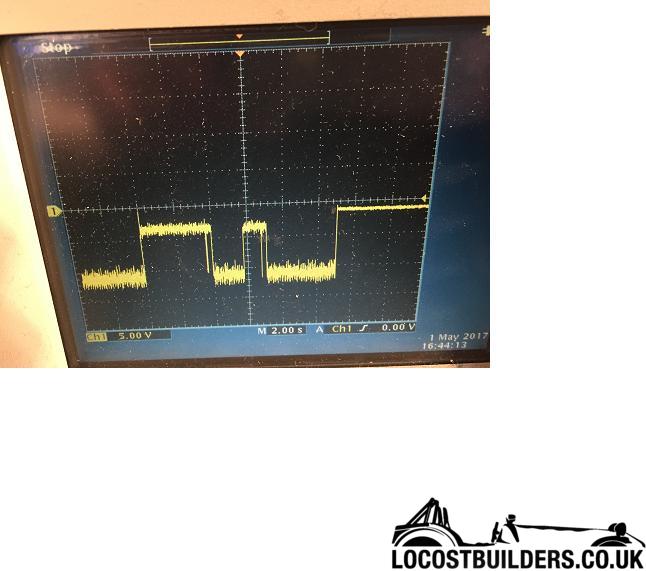
I have a Signal that is reading a negative voltage. I wish to condition it so i can read the Anologe Voltage wit my PIC.

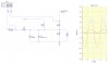
Can anyone help me on how to condition the signal to get a positve voltage in reference to graund.

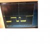
Signal below. would like a 0 - 5v Representation of this signal?

Thank you

Gear Signal.JPG
 

Attachments

  • Gear Signal.JPG
    Gear Signal.JPG
    48 KB · Views: 106
Also using basic components would be great. I'm trying to get this working today so wont be able to buy any components today, if i need to buy some differnet components then I will have to get this working over the week.

Any help would be amazing.

Jason
 
Do you have a negative supply in your system?
 
No.
 
FYI

This signal can vary to about -17V.
 
How do you get a signal that can go to -17 V without a negative voltage power supply somewhere in the system?

ak
 
I'm measuring a signal from my car. So I don't exactly know the source of the signal. In the system I'm building I do not have a negative Power Supply.

I think I have come up with a solution and wonder if anyone could check it. Please see attachment. Let me know if this would work to connect to my ADC of my PIC.

Thanks for everyones help so far,
 

Attachments

  • cct idea.jpg
    cct idea.jpg
    144.8 KB · Views: 134
Even simpler, how about this for a 0V to -20V input?
NegToPos.PNG
 
Try this:

44.png
 
Gents,

I alittle confused,

The signal I have from the vehicle are 2 wires. Let's call it signalA and SignalB.

If I measure signalA in reference to signalB I measure a constant 15V with no stepping. If I measure SignalB in reference to signalA I measure the original attachment above.

I need to see the stepping as this is the condition I'm trying to monitor.

So it's not as simple as measuring the negative voltage because I cannot join the grounds together. Does this make sense

Jason.
 
Hello,

Your original post showed only one signal, now you say there are two, so you confuse everyone here.

If you have two signals instead of one, you must show both and show what you need out.
If you have a negative signal it's easy to convert to a positive signal only, but you need to explain this second wire. I am sure everyone here assumed you mean the negative signal wzs with reference to ground which is 0 volts.
 
Hello,

...I am sure everyone here assumed you mean the negative signal wzs with reference to ground which is 0 volts.
Yep, that is what I assumed...

Use both channels of your scope to display A vs carGnd, and B vs carGnd. (I assume your Pic will eventually be connected to carGnd). This means connecting the scope ground to the car body while making the measurements.

If your scope has the capability, display a single trace which is A-B (differential), but I also what to see the two individual traces.
 
Last edited:
Gents,

Sorry didn't realise until I started to try a practical example of the cct's above. Then realised that my grounds are different.

I'll do some more measurements as suggested by Mike, but if i remeber correctly the results are basically

The condition is when I put my vehicle into Gear!

SignalA in reference to VehicleGrd - constant 14v (basically vehicle battery) with no step on the condition
SignalB in reference to VehicleGrd - 0v with no step on the condition.

SignalB in reference to SignalA -14v with step on condition.

But I'll confirm all these tomorrow, as I cannot start the car tonight because it's very loud.

I seem to only get the step on the SignalB in reference to SignalA.

Jason.
 
Ok. I can do it withgout the engine started, just a lower voltage due to the alternator not running.

Measurement 1
Channel 1 - Signal B refernce to Signal A
Ap Approx 6 seconds, igntion on
At Approx 9 seconds, selected 1st Gear
At Approx 14 seconds, selected Netueral

upload_2017-5-1_23-54-46.png


Measurement 2
Channel 1 - Signal B Reference Vehicle Ground
Channel 2- Signal A Reference Vehicle Ground

At approx 8 seconds - Ignition On

On selection of Gear - No Change

upload_2017-5-1_23-57-24.png


I hope this all makes sense now....

Note : In Measurement 1 it is alittle different when the vehicle is started - See original post #1

Jason
 
This does NOT make sense. Look at the lower scope picture. CH1 (yellow:B) is 0V for 20s. CH2 (blue=A) starts out ~1V, and then switches to ~10V +- 1V of noise at 7.5s. The upper photo does not show the difference between CH1 and CH2; it shows something different.

I am thinking that at least one of the signals are coming from an open-collector type output, and you need a pull-up resistor to reveal the true nature of the signal.

Try connecting a 10K to 100K resistor between A and B, and then show us A and B wrt carGnd again.
 
This does NOT make sense. Look at the lower scope picture. CH1 (yellow) is 0V for 20s. CH2 (blue) starts out ~1V, and then switches to ~10V +- 1V of noise at 7.5s. The upper photo does not show the difference between CH1 and CH2; it shows something different.

I am thinking that at least one of the signals are coming from an open-collector type output, and you need a pull-up resistor to reveal the true nature of the signal.

Totally agree, I couldn't understand the how the seperate signals combine to the original post. All I know is, I need to see the vehicle is in gear and the original post shows this but as a negative voltage.
Any ideas?

Jason.
 
Totally agree, I couldn't understand the how the seperate signals combine to the original post.
The input resistance of the scope is either 1meg or 10meg per channel. The two input resistances act in-series as a 2meg or 20meg pull-up provided you let the chassis of the scope float with respect to carGnd. The reading likely is bogus...


All I know is, I need to see the vehicle is in gear and the original post shows this but as a negative voltage.
Any ideas?

Jason.
I already told you. Hook a 10K to 100K resistor from A to B and then post V(A) and V(B) with the scope ground connected to the car.
 
Status
Not open for further replies.

Latest threads

New Articles From Microcontroller Tips

Back
Top