Continue to Site

Welcome to our site!

Electro Tech is an online community (with over 170,000 members) who enjoy talking about and building electronic circuits, projects and gadgets. To participate you need to register. Registration is free. Click here to register now.

  • Welcome to our site! Electro Tech is an online community (with over 170,000 members) who enjoy talking about and building electronic circuits, projects and gadgets. To participate you need to register. Registration is free. Click here to register now.

Filtering for a signal level detector

throbscottle

Well-Known Member
I'm making an analogue tachometer for my PCB drilling machine, but the level detector at the end isn't very good - help please!

Here's the setup: The 5 pole motor is driven by a 10KHz PWM signal and does up to 30K RPM. The actual adjustment range starts at about 10K I think.

A 0.1 ohm sense resistor in series with the motor picks up commutator switching and PWM, and goes through a RC filter to get just the commutator signal. This is amplified and turned into pulses to drive a 555 monostable.

So this gets me an extremely jittery PWM signal relating to the speed of the motor, which is fed into a level detector consisting of a diode feeding a 10uF capacitor with a 100k resistor across it. These are just junk-box values I had to hand.

The change in voltage over the speed range is tiny (maybe 50mV), so for one thing I'm hoping someone can suggest a better system! In the absence of a better system, what's a good strategy for filtering the noise from the output what won't slow down the response too much?
 
Can you just put a reflective marker on the shaft and use a photo detector
or interrupter to measure RPM ?


Your method I think deeply affected by electrical and switching noise, hence jitter
in measurement predominant.


Regards, Dana.
 
If the motor is running at 30,000 rpm, that is 500 Hz. You would need to allow though 500 Hz and filter out the 10 kHz of the PWM. You should filter the signals with a cut-off around 1kHz. However if you are measuring a voltage from a current shunt, that will be quite small while the PWM at 10 kHz will be a lot larger. The best that you can hope for with an RC filter is to get 10 times less signal at 10 kHz, but if the 10 kHz is much larger than the current shunt signal in the first place, the current signal will be swamped by the PWM voltage anyhow.

A differential amplifier across the current shunt would help to remove the voltage signal that will be mostly the same on either side of the current shunt.

You could use a Hall-effect current sensor.
 
500 revs per second, not 500 Hz. 5 pole commutator gives 10x value (apparently). Makes it tricky. I was quite surprised that my simple filter worked at all, it was only a crude test - I'd got a 3 stage active filter design lined up fresh from TI's web-bench - but then didn't build it!

Anyway, Dana, I didn't want an extra thing attached to my spindle, so not using optical etc. - it means an extra assembly attached to the drill head and another set of moving wires. Though a paint dot would be ok if I was going to do that. Quite apart from which, I want an analogue meter for my display, something like a car's tacho. Maybe it would still be easier with a M/C, I don't know.

Hall effect current sensor. Ok - but won't that produce a similar kind of signal to what I'm already seeing? Would eliminate the hot shunt from the board though. Shame I don't have one in my junk box, it's a very attractive idea. Motor draws around 3A so plenty for it sense!

I'll certainly have a play with the diff-amp idea. Will have to move the shunt to high side, is currently 0v at one end. Never remotely occurred to me there might be an advantage in doing it another way.

Another thing that occurred to me was, what if I attempt to subtract the PWM signal from the shunt signal - a bit like extracting Stereo from FM?
 
Commutator noise is next to impossible to reliably filter. Commutator sparking is very significant and is dependent on the torque required from the shaft.
A successful solution which I have seen applied is to interrupt the power for a few milliseconds, such that there is no current flowing in the rotor and thus no or minimum sparking, and then in that period, read the motor's back-EMF voltage.
But that trick will only work with a permanent magnet motor or a shunt-wound motor whose field is powered independently from the armature supply.

But hey! I know you will ignore my advice. Please continue with your analog filter idea.
 
From what I have seen of DC motors, the brush ripple is quite large compared to the normal current if they are running at light load. However I have only seen that were the PWM frequency is a lot higher than the frequency of the brush ripple.

The motor inductance is big enough that you won't get much PWM noise in the current, as long as you can measure current without the PWM voltage making much difference.

You could just measure the average voltage. Filter out anything above a few Hz, and at light load, the voltage will be a reasonable measure of the current.

edit: I've just realised that the last sentence should read:- Filter out anything above a few Hz, and at light load, the voltage will be a reasonable measure of the speed.
 
Last edited:
Ok, so it's a permanent magnet motor, lightly loaded. Pretty sure it has an anti-spark ring.

Periodic interrupts are possible but mean adding at least 1 extra connection to the main board, and providing some means of remembering the values. Also I'm not sure if the IRF21531 half-bridge driver controlling the speed will shut off both transistors so the motor can coast. I think it can only brake. Anyway I'll set up another motor and experiment with the approach and see what happens - it would be interesting to see it working. I'm going to have to change the board layout at some point anyway so we'll see.

The signal from the shunt is very noisy - on the 'scope it didn't look like I'd get anything useful from it. Not sure I want to mess about changing an 0603 capacitor to increase the PWM frequency if I can avoid it. Maybe try with a separate controller..

So maybe worst is best - get the average voltage and see where that leads. I was put off the idea at the start because it's also load dependent. Ok with normal PCB sized drills but loading is noticeable with 2mm+. Good job it doesn't need to be accurate!
 
Anyway, Dana, I didn't want an extra thing attached to my spindle, so not using optical etc. - it means an extra assembly attached to the drill head and another set of moving wires. Though a paint dot would be ok if I was going to do that. Quite apart from which, I want an analogue meter for my display, something like a car's tacho. Maybe it would still be easier with a M/C, I don't know.

Another possibility is white dot on chuck/spindle, and a low power laser diode, like in a pointer,
and detect reflective pulse with opto sensor. Just a thought in case the filtering problem simply
not feasible. This also gives, like hall effect, a simple RPM based signal independent # poles. Laser
has advantage does not have to be close like hall, but does have to have a clear optical path. Hall
does have ease of adapting to tooling, if new tooling required a change in sensor position due to
obstructive interaction with new tooling.
 
Last edited:
Back-EMF is not load dependent on a permanent magnet motor or separately biased shunt wound. It is directly proportional to rotational speed only.

But you haven’t told us the motor type, it could be a series-wound (universal) motor fed from AC.
 
Hi schmitt trigger. It's a permanent magnet motor fitted with anti-spark ring I believe.
I get discernible pulses from the commutator switching but there is a lot of noise as well, including I have realised, PSU noise as well as the PWM noise. It's pretty horrible.
I did try diver's suggestion of filtering down to DC but there's a hump so that's no good. Diff amp next.
I started setting up an encoder to measure the speed accurately (as a reference more that permanent fixture) but noise bites even there. Anyway between my knackered knee and covid I haven't got round to continuing with it. Might be what I end up using after all.
It doesn't have to be accurate when it's done, is just a guide. Hence not wanting to go down the encoder route.
 
Last edited:
I have a vintage version of one of these. Amazing machines and fun to use or demonstrate with students and interns. Current OSHA regulations really limits points where one can interfact with rotating equipment (rightfully so) but some safe points do exist without fear of injury. Your home use is different and interesting results can be obtained.

 
Well, things are looking a lot better! I set up a diff amp as the input, unity gain, and the worst of the high frequencies disappeared! So thanks for that diver, sound advice. Next, single stage gain just over 2, feeding a 2 stage RC filter (3k+10n then 1k+100n). Resulting signal is discernible 10 pulses per revolution, sitting in a ramp-ish formation that follows each revolution.

I got my reference tacho working using a 60 slot encoder and a couple of npn's. The 60 slot encoder enables a direct speed reading using a frequency counter. Unfortunately it's held in a mandrel in the drills chuck so I can't drill and measure at the same time...

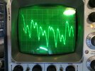
Photo of scope screen shows speed around 16k RPM. The double peaks resolve to better defined pulses at higher speeds and tend to merge more at lower speeds. Also at lower speeds the per-revolution wave looks more like a ramp, but at high speeds it looks like a hump. I'm wondering if that's an artefact of the LM324's bandwidth though.
IMG_3228.jpg
At 20K RPM I counted 10 pulses in 3mS, which I was amazed to discover corresponds near enough to the actual speed!

So anyway better filtering and more gain to follow...

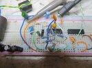
Photo of breadboard - just for show.
IMG_3226.jpg
 
In case anyone is still interested...

I made it work in LTSpice - 3 signals do a rough approximation of what I'm getting from the motor. Diff amp, low pass then high pass filters, boost to a somewhat untidy pulse train, 555 to convert the signal to PWM, filter, level shift and amplify. Not sure if choosing a jfet to drive the meter is a good idea but I get the kind of output I want.
 

Attachments

  • LM324.txt
    1.1 KB · Views: 40
  • Draft5.asc
    6 KB · Views: 34
Last post on this topic.

I eventually obtained nice pulses from the motor's commutator, with the high pass filter first to get rid of the once-per-revolution "rumble" and the worst variation in pulse size. After that the noise from PWM was easily removed with just the 330uH + 1.8uF combo.

At no point has noise from sparking been an issue.

Unfortunately the number of pulses varies with changes in motor speed. Inserting a lot of gain in the system lessens the effect, but can't remove it.

So the result was that the output would actually dip during most of the mid-range motor speed, with the low and high ends being fairly close in output. Oh well.

So I'll try to attach an optical sensor somewhere. Very annoying...
 

Latest threads

New Articles From Microcontroller Tips

Back
Top