Skyknight
New Member
Hi there!
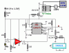
I've got the following circuit built onto a PCB, and I have the following problem:
Depending on the entries (pins 3, 5, 6 and 7 of the PIC) the output (pin 2) must be set (5V) or clear (0V). This pin must activate the relay in one of those cases (I don't matter which, just one of them).
The problem: I always get a high level (5V) independently of the entries. I measure this with a multimeter just in the pin 2 of the PIC.
The question: Is the arrangement wrong? Can anyone suggest an alternative for the arrangement? Is the relay correctly used?
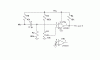
Some comprobations I've made:
I took off the PNP 557 and I could register sometimes 0V.
Too, I've changed the program of the PIC until it was so simple that an error would be almost impossible.
I've changed the PIC by a new one (twice).
And I've changed the PNP 557 too.
I tested I wasn't making a mistake with the order of pins of the PNP.
I tested the PCB draw and it fits the schematic.
The resistor is really a 4K7 ohm resistor.
I could light a LED through pin2 taking off the PIC and conecting it into a ProtoBoard.
Please, I need urgent help. Now I'm totally confused. I don't know if it is an analog problem, or digital. I don't know if it's a hardware problem or software.
S O S
I've got the following circuit built onto a PCB, and I have the following problem:
Depending on the entries (pins 3, 5, 6 and 7 of the PIC) the output (pin 2) must be set (5V) or clear (0V). This pin must activate the relay in one of those cases (I don't matter which, just one of them).
The problem: I always get a high level (5V) independently of the entries. I measure this with a multimeter just in the pin 2 of the PIC.
The question: Is the arrangement wrong? Can anyone suggest an alternative for the arrangement? Is the relay correctly used?
Some comprobations I've made:
I took off the PNP 557 and I could register sometimes 0V.
Too, I've changed the program of the PIC until it was so simple that an error would be almost impossible.
I've changed the PIC by a new one (twice).
And I've changed the PNP 557 too.
I tested I wasn't making a mistake with the order of pins of the PNP.
I tested the PCB draw and it fits the schematic.
The resistor is really a 4K7 ohm resistor.
I could light a LED through pin2 taking off the PIC and conecting it into a ProtoBoard.
Please, I need urgent help. Now I'm totally confused. I don't know if it is an analog problem, or digital. I don't know if it's a hardware problem or software.
S O S
")
