Continue to Site

Welcome to our site!

Electro Tech is an online community (with over 170,000 members) who enjoy talking about and building electronic circuits, projects and gadgets. To participate you need to register. Registration is free. Click here to register now.

  • Welcome to our site! Electro Tech is an online community (with over 170,000 members) who enjoy talking about and building electronic circuits, projects and gadgets. To participate you need to register. Registration is free. Click here to register now.

Unexplained changes in circuit output

Status
Not open for further replies.
I've scanned this thread and it seems that one important troubleshooting basic hasn't been mentioned. Apologies if I missed it. When a circuit like this isn't doing what you expect, the first thing to check is the "reference". In this case that is the input node of the op-amp (or comparator) that is connected to the POT. That shouldn't be moving with outside temperature changes, so if the regulating temperature is different at different times, compare the voltage at the pot-connected amp input at the two times. If that changes, then that's your problem. Then you need to figure WHY it's moving around with outside temperature. That's place to start. You need a decent 3 1/2 digit DVM to do this. These circuits are not that hard to trouble-shoot, start at the reference and work outward. Don't "shotgun" it. The reference is the point that telling the circuit what to do, in this case it's the pot voltage.
 
Hi

I am not ignoring your recommendations but you will understand I have to find existing circuits to modify due to my skill level, could find no complete circuits using the MOC3081. In my hunt I have located one that hopefull could do what I want, it is also a Proportional Control Triac Triggering Circuit that appears to be Zero Crossing. https://www.electro-tech-online.com/custompdfs/2009/10/TDA1023_T_CNV_2-1.pdf This is more for me as hopefully I can calculate the values based on the data sheet and don't have to design ..... that is of course assuming the circuit is appropriate.

They quote 5 to 30°C control range, surely this can this be altered, could not find anything.

They speak of special capacitors?

They appear to have two thermistors?

I have included a schematic from their datasheet.

Cheers
Andrew

hi,
Looks OK, give it a try, lets know how it goes.:)
 
Hi Eric,

my last post was in cyberspace when you posted. Ignore last post. Would prefer to use your original comparitor circuit as at least I got to understanding comparitors. Additionally the board is half designed already.

Would love to have to files to play around on LTS. Can you see my e-mail address your must I PM you with it.

Cheers
Andrew
 
I've scanned this thread and it seems that one important troubleshooting basic hasn't been mentioned. Apologies if I missed it. When a circuit like this isn't doing what you expect, the first thing to check is the "reference". In this case that is the input node of the op-amp (or comparator) that is connected to the POT. That shouldn't be moving with outside temperature changes, so if the regulating temperature is different at different times, compare the voltage at the pot-connected amp input at the two times. If that changes, then that's your problem. Then you need to figure WHY it's moving around with outside temperature. That's place to start. You need a decent 3 1/2 digit DVM to do this. These circuits are not that hard to trouble-shoot, start at the reference and work outward. Don't "shotgun" it. The reference is the point that telling the circuit what to do, in this case it's the pot voltage.

Hi,

I believe the circuit is doing exactly what it should be doing. The problem rests with the hysteresis in the heating element due to the delay in getting up to temperature. It would be correct I believe, to state that my original circuit is not appropriate to addressing the element hysteresis (which was established only later) and that the problem all along was not the circuit but the element lag. On a compressor fridge the unit works a real treat. The last suggestion from Eric on proportionl control is in fact the correct solution I believe.

Cheers
Andrew
 
Hi Eric,

my last post was in cyberspace when you posted. Ignore last post. Would prefer to use your original comparitor circuit as at least I got to understanding comparitors. Additionally the board is half designed already.

Would love to have to files to play around on LTS. Can you see my e-mail address your must I PM you with it.

Cheers
Andrew

hi Andrew,
Here are all the LTS files for your project, red and raw.:rolleyes:

You will need to get the LM393 and MOC models etc from Yahoo groups LTSpice.
Put the models etc, into LTS folders so that the asc files have access.

If you get stuck, ask.
 

Attachments

  • Andrew1.zip
    16.7 KB · Views: 117
Hi Eric,

A whole bunch of things.

1.) Cannot extract the file under Winzip it tells me it is invalid?

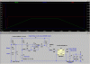
2.) If I try interpret the graphs.

- V(thntc) is low so Q1 and MOC3081 goes high. Current flows for a period of ~95 milliseconds before V(thntc) goes high.
- V(thntc) goes high, the rest goes low and current no longer flows for a period of ~110 milliseconds.

So the switching rate is roughly every 100ms to maintain a temperature that will correspond with the combined resistance of R9 and R10 =14.5k which is a temperature of 2.5°C?

3.) Although 2.5°C is the required temperature at the crisper area of the fridge the measurement is taken from the evaporator unit which is cooler by what appears to be 8°C based readings taken. That means V9 and V10 will need to total in the order of 25k in order for the the evaporator to be at -7°C so that the fridge can be at a max of 1°C. So when I play with LTS the two pots will change to 25k and 5k?

4.) The way I understand it the MOC3081 is basically a low power SSR?

5.) If I look at the latest schematic you sent, R5 appears to be the 175W heater, the value of 350 Ohms confused me?

6.) As the MOC3081 is able to cope with 1.2A this should be fine to drive the 0.8A of the heater. I did notice a caveat on the data sheet "The optoisolator should not be used to drive a load directly. It is intended to be a trigger device only". Does than mean we need to add the Triac as per the data sheet? That would also allow me to drive with the freezer on.

7.) The old circuit was not the best I do understand but theoretically I had the hysteresis such that the on and off voltage were 6.39V and 6.25V, thats tight. Why then was the relay not chattering away as the unit switched on and off. Have any idea?

8.) It is OK for the 12V to share a common ground with 220V?

You are going to need that holiday after all the work you are doing for me:D.

Cheers
Andrew

PS: Are you familiar with chemelec's inverter, **broken link removed** I did the revised circuit. Is this OK for my heater supply.
 
hi,
I have just unzipped the zipped file without any problems, its the same zipper program I always use on the forums, as far as I know no one else has had a problem.?

Its important to note as the text says on that last circuit, its exactly the same operation as the relay version with regard to the switching points, only the relay has changed.

I would use the MOC to switch a higher power triac or use the Sharp S102S02 directly to power the load.
 
Last edited:
Hi,

the properties of the Zip file show that there is "no zip file, bad zip file or part of spanned zip file" the file is 17k in size. Think it may have got corrupted enroute. I have downloaded it numerous time with the same result. Would you care to send it again please.

Cheers
Andrew
 
Hi,

the properties of the Zip file show that there is "no zip file, bad zip file or part of spanned zip file" the file is 17k in size. Think it may have got corrupted enroute. I have downloaded it numerous time with the same result. Would you care to send it again please.

Cheers
Andrew

hi,
I have pretested unzipping OK.

EDIT: How was it for you....:rolleyes:
Did it read OK.?
 

Attachments

  • Andrew1(2).zip
    16.7 KB · Views: 128
Last edited:
Hi Eric

Downloaded Winzip 14.0, the latest version, the same result. What program did you use?

Cheers
Andrew

hi,
I use IZarc to zip.

I'll post each file as asc.
Some are just rough sims.

EDIT:
dump the Andrew2.asc... I was trying an idea.
 

Attachments

  • AndrewTriac1.asc
    3.8 KB · Views: 173
  • AndrewTriac2.asc
    4.5 KB · Views: 149
  • Andrew5.asc
    4.7 KB · Views: 146
  • Andrew1.asc
    3.5 KB · Views: 162
  • Andrew3.asc
    3.8 KB · Views: 131
  • Andrew3t1.asc
    5.8 KB · Views: 199
  • Andrew3t2.asc
    4.6 KB · Views: 145
  • Andrew4.asc
    3.5 KB · Views: 173
  • Andrew4a.asc
    3.6 KB · Views: 170
Last edited:
Hi Eric,

thanks.

Have logged onto the yahoo group. Have found the LM393 and the MOC308x series but can't get the .sub files. Can these be created from the .txt files?

In the meantime using the LM339 as it has a .sub file but I am being stopped at the opto.

Cheers
Andrew
 
Hi Eric,

thanks.

Have logged onto the yahoo group. Have found the LM393 and the MOC308x series but can't get the .sub files. Can these be created from the .txt files?

In the meantime using the LM339 as it has a .sub file but I am being stopped at the opto.

Cheers
Andrew

hi,
All the files you need are here, get them all
**broken link removed**
 
Hi Eric,

progress but can only get one cycle of current to the heater then it switches off?

Hey, this could be a bunch of fun and a great learning tool.

Cheers
 

Attachments

  • My Version.gif
    My Version.gif
    31.1 KB · Views: 161
Hi Eric,

progress but can only get one cycle of current to the heater then it switches off?

Hey, this could be a bunch of fun and a great learning tool.

Cheers

hi,
Post your version of the asc file.
I see that you are using a LM339.???

Use Tools/Control Panel and change the plot background to white so that its easier to read.
 
Last edited:
Hi,

will do.

In the files I could only find the LM339.asy file , got it "working" and in my excitement forgot to go back and track down LM393A. Will go and find it, correct the background and post.

Cheers
 
Hi,

will do.

In the files I could only find the LM339.asy file , got it "working" and in my excitement forgot to go back and track down LM393A. Will go and find it, correct the background and post.

Cheers

hi,
It works for me.??
 

Attachments

  • AndrewTriac1b.gif
    AndrewTriac1b.gif
    38 KB · Views: 149
Last edited:
Status
Not open for further replies.

Latest threads

New Articles From Microcontroller Tips

Back
Top