Continue to Site

Welcome to our site!

Electro Tech is an online community (with over 170,000 members) who enjoy talking about and building electronic circuits, projects and gadgets. To participate you need to register. Registration is free. Click here to register now.

  • Welcome to our site! Electro Tech is an online community (with over 170,000 members) who enjoy talking about and building electronic circuits, projects and gadgets. To participate you need to register. Registration is free. Click here to register now.

Unexplained changes in circuit output

Status
Not open for further replies.
Hi Eric,

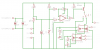
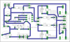
I lied to you, the thermistor reads 14.4k @ 3.0 deg C. Was measuring in circuit, took it out of circuit now and that is the reading. My memory is poor but now it is coming back to me. The thermistor value at the target temperature needed to be as close to 15k in order to balance with R1. Apologies for that.

Have finally found the spec https://www.electro-tech-online.com/custompdfs/2009/10/LeadedDisks__B57164__K164.pdf . Mine is the J series which makes it 5% tolerance.

Hope this helps

Thanks
Andrew
 
Last edited:
Hi,

another question. When using screw connector blocks on a PCB for offboard components. Is it good or bad practice to solder the ends of the connector wires or should these be simply stripped of insulation and inserted into the blocks and screwed tight?

Mine are all soldered!

Andrew
 
Hi,

another question. When using screw connector blocks on a PCB for offboard components. Is it good or bad practice to solder the ends of the connector wires or should these be simply stripped of insulation and inserted into the blocks and screwed tight?

Mine are all soldered!

Andrew

hi,
I prefer to solder the strands before using terminal screw blocks.:)

I have analysed the circuit, its got a very poor spec, the hysteresis is changing as the thermistor changes value and the Vsetting is coarse.
I could make a few suggestions that will improve it. if required.
 
Hi Eric,

Would really like to have any suggestions that you may have. I will have this working correctly, it is a matter of principle.

Thanks
Andrew
 
Hi Eric,

Would really like to have any suggestions that you may have. I will have this working correctly, it is a matter of principle.

Thanks
Andrew

FWIW, I believe I would start any redesign by substituting a good comparator for the 741. I have found the 741 to be very unreliable when used in single supply mode.
 
FWIW, I believe I would start any redesign by substituting a good comparator for the 741. I have found the 741 to be very unreliable when used in single supply mode.

hi AllVol,
I agree, this would be the first modification, I think its already been suggested earlier in the thread.

I use the LM393 as general purpose compartor.

Regards
 
Hi Eric,

Would really like to have any suggestions that you may have. I will have this working correctly, it is a matter of principle.

Thanks
Andrew

hi Andrew,
Are you prepared to do a complete rebuild using a LM393 comparator.?:)
 
Hi Eric,

absolutely. I would not expect people to put in the effort without honouring that. In any case I really want this thermostat to work as I had originally intended.

Instead of having two circuits, one for 220V and one for 12V is it possible to have one circuit switching both a 220V 175W and when required to switch the 12V 175W element. I don't mind altering the power in to be fed by the 12 V caravan battery alone and to dispense with the 220V step down supply. It would make sense as surely the control circuit can feed both relay. I don't have the knowhow to mix 12 abd 220V.


Am I being cheeky?
Cheers
Andrew

hi,
Look at this option, its gives the ~5K operating point for the Therm resistance that you have measured.
The +12V supply should be regulated.
 

Attachments

  • Andrew1.gif
    Andrew1.gif
    32.2 KB · Views: 123
Last edited:
Hi Eric,

Check post #21 where I had made an error in the measurement of the thermistor, I had measured in circuit rather than out of circuit. The resistance at target temperature of 3 deg C is ~ 14.5k. I should have caught it, NTC, the resistance should have increased as the temperature decreased. What needs to change?

The two pots (10 and 2k), are you showing the theoretical resistance that one needs to dial in to get the desired result? Is the one coarse and the other a fine adjustment?

When I get home will get the board done and will pass it by you.

Thank you very much for the effort.

Cheers
Andrew

hi,
Thanks for the corrected figures.:)
I will edit the circuit and repost.
The 10K and 2K are coarse and fine [the fine pot is external]

One point I need to clear up, is the relay n/o or n/c when NOT energised, the switching sense seems to be wrong for a n/o relay.?
 
hi,
Look at this modified circuit.
Rtherm= 14k5 at 3Cdeg.
 

Attachments

  • Andrew3.gif
    Andrew3.gif
    38 KB · Views: 139
Hi Eric,

thanks for that. The relay needs to N/O when not energised. The heating element has to be energised to cool the fridge.

Nearly done with the board.

Cheers
Andrew
 
OK,

was trying to get clever here. Could you please check the following?

1.) Wanted the have 12 and 220V element capabilitiies so I put in a selector switch after the 2N3906 to drive either one of two SS Relay's. I don't know if this is possible?
2.) Wanted to have a visual display of which relay was working so put in two LED's and resistors, will they work as inserted?
3.) Will the 2N3906 drive a typical SS Relay? And will the output of the one SS Relay drive that automotive relay that will be off board?
4.) Was I correct to omit the diode protecting the relay as there appears to be an internal diode on the SS Relays?

Thanks
Andrew

PS: Connector X3 feeds the coil of the 12V Automotive Relay
 

Attachments

  • Erics Schematic.png
    Erics Schematic.png
    12.8 KB · Views: 134
  • Erics Circuit Board.png
    Erics Circuit Board.png
    19.4 KB · Views: 129
Last edited:
OK,

was trying to get clever here. Could you please check the following?

1.) Wanted the have 12 and 220V element capabilitiies so I put in a selector switch after the 2N3906 to drive either one of two SS Relay's. I don't know if this is possible?
2.) Wanted to have a visual display of which relay was working so put in two LED's and resistors, will they work as inserted?
3.) Will the 2N3906 drive a typical SS Relay? And will the output of the one SS Relay drive that automotive relay that will be off board?
4.) Was I correct to omit the diode protecting the relay as there appears to be an internal diode on the SS Relays?

Thanks
Andrew

PS: Connector X3 feeds the coil of the 12V Automotive Relay

hi,
I didnt know you had decided to use SS relays!.:)

Your circuit with the SSR's its very wrong, dont build it that way.

EDIT: you are showing SSR 'ac' type relays, I thought the fridge heater was 'dc'
 
Last edited:
Hi,

OK here is the way you intended. I hope;

-please check the if the dual relays will work with that switch and if the LED's will operate correctly to indicate which relay is functional.
-will the the one relay be OK to pull in the automotive relay (think it was an 80 ohm coil). I can't see any issues with it as it is acting as a switch rather than having to power a coil. The contacts are X3.

Thanks
Andrew
 

Attachments

  • Erics Schematic V2.png
    Erics Schematic V2.png
    12.5 KB · Views: 127
  • Erics Circuit Board V2.png
    Erics Circuit Board V2.png
    17.8 KB · Views: 120
Hi again,

with regard to the relay contacts ..... trick question.

When the circuit is sending no signal the relay will be open circuit, when the relay activates then contact close to make circuit. When there is no power to the circuit the relay must remain open as a fail safe measure. Hope that is how I explained it first time round.

Cheers

hi Andrew,
Ran some calculations on your thermistor using the standard parameters, I get a resistance value of 25K at +5Cdeg.
Where have you mounted the thermistor in the fridge in order to get 14.5K at +5C..??
 
Hi Eric,

sorry for the delay, we broke camp this a.m. and towed back to JHB, a 5 hour ride.

The thermistor was positioned at the lowest steel grid shelf about 1cm from the hermetically sealed remote temperature probe. I have not mounted it yet as I wanted to conclude my experiments first.

Cheers
Andrew

It was 14.5k at 3 deg C.
 
Last edited:
Status
Not open for further replies.

Latest threads

New Articles From Microcontroller Tips

Back
Top