Continue to Site

Welcome to our site!

Electro Tech is an online community (with over 170,000 members) who enjoy talking about and building electronic circuits, projects and gadgets. To participate you need to register. Registration is free. Click here to register now.

  • Welcome to our site! Electro Tech is an online community (with over 170,000 members) who enjoy talking about and building electronic circuits, projects and gadgets. To participate you need to register. Registration is free. Click here to register now.

ultrabrightLED flashlight

Status
Not open for further replies.
MStechca,
Zack's LED is already a low voltage indicator. It becomes very dim when his 3V battery's voltage sags below about 2.8V. :roll:
He needs a step-up current regulator that switches for high efficiency and varies its duty-cycle to maintain the LED's current as the battery runs down. :lol:
 
Hey audio, im not sure how you're confused? The LED im using is from allelectronics, I provided a link to it @ the beginning of the thread, thats the one im using. I think the reason you think im using a smaller beam angle is that I put the LED in a reflector from a maglite, which would give me a smaller beam angle.

Hmm, my batteries must have been low because when I first got the thing, I hooked it up to the batteries w/ a resistor and kept lowering the resistance till i realised that I didn't need a resistor at all. I have to check those batteries' voltage.

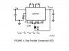
Thermal connection to the case should be made.
How do I do that Oznog? I plan to put the LED in a maglite flashlight, I'm sure I could use the aluminum flashlight case as a heatsink...

Alrighty than, Ill just have to order those parts for the chip-torch and it looks like ill be in business :lol:

I really need some input on my idea of direct driving the LED (with a resistor of course :lol: ) until it becomes dim, and then using the chip-torch circuit.

I think I confused everyone earlier when I said I was going to use the DC-DC converter, i meant the chip-torch. The ciruit that chiba provided.

EIDT: Last night i was bored and decided to see just how much current an incandescent light bulb would pull. I read around 900mA!!! If I draw 150mA max, that means I can have a flashlight that will last 6 times as long, at around the same intensity of light! im pretty stoked.
 
Hi Zach,
I got confused because you said you fitted a "Luxeon" In your Maglite. A Luxeon has a built-in heatsink.
Your Cree XLamp is designed to be soldered to a pcb and uses the printed copper as its heatsink.

Since the beam is "only" 100 degrees, very little light will be reflected from a flashlight's reflector. The Luxeon is focused to a fairly narrow angle.

Just use the Silicon Chip torch circuit without a switch for "Direct From The Battery", or "Boosted". Even a Mosfet as a switch will produce loss. You don't have enough voltage to drive the gate of a Mosfet anyway.
 

Attachments

  • cree_xlamp.png
    cree_xlamp.png
    59 KB · Views: 854
Just use the Silicon Chip torch circuit without a switch for "Direct From The Battery", or "Boosted".
Not sure what you mean by this: Should I have a switch or not? I just plan on having a SPDT switch to switch between regulator and direct from battery. How does a MOSFET come into play???

My Cree Xlamp is already soldered to the aluminum PCB heatsink, it came that way. Oznog said I will need further heatsinking besides this, how am I to do that?

Actualy, the reflector makes a HUGE difference in directivity and I am going to use it.
 
zachtheterrible said:
Should I have a switch or not? I just plan on having a SPDT switch to switch between regulator and direct from battery.
With a switch you will have no control over the current that is very sensitive to battery voltage. The LED will fry if the voltage is too high for it. The voltage from brand new battery cells is much higher than you have now. Don't use a switch!

How does a MOSFET come into play???
I was thinking you wanted to switch automatically, by sensing the battery's voltage.

My Cree Xlamp is already soldered to the aluminum PCB heatsink, it came that way. Oznog said I will need further heatsinking besides this, how am I to do that?
Cree's datasheet shows that it needs to be soldered to a pcb so that it can use the pcb's copper as a heatsink, when its current is more than about 150mA.

Actually, the reflector makes a HUGE difference in directivity and I am going to use it.
OK, but I don't see how since hardly any light will radiate sideways to the reflector.
 
Hi Zach,
Lots of confusion is ended. Look what I discovered:
 

Attachments

  • cree_pictures.png
    cree_pictures.png
    154.9 KB · Views: 845
That's not a heatsink, THIS is a heatsink :)
 

Attachments

  • ath_652453b12000.jpg
    ath_652453b12000.jpg
    17.7 KB · Views: 833
Hi Chiba,
I don't think Zach should put a couple hundred Watts into his little LED! :lol:
 
I found a place with some LED driver circuits das ist in German, Yar. I can make out what they are on about and they have a step-up (Vampirschaltungen) luxeon circuit (i know zachs isn't a luxeon, but close) that they claim is 90% efficient and usefull down to 1.9V.

Original page in German:
http://www.led-treiber.de/html/getaktete_treiber.html

If you don't read German tanslate the page:
http://translate.google.com/translate_t

Bench testing above LED array :)
 

Attachments

  • bench-test.jpg
    bench-test.jpg
    13.9 KB · Views: 815
williB, That driver is only good for ~80mA when paralleled, I don't think that's enough to drive zachs' LED? even with a 3.6V input the best you could get from it would be ~0.4watt, NiMH or Nicads probably would work at all?

It would be great driving 4 20ma LED's from a lithium battery though :)
 
Yep thats an wierd pakege (It reminds me of an PC CPU since they are in simalar packeges but whith a LOT more pins)

Meaby you shod work whith WilliB since he has an project whith an LED flashlight (Only he ran it on super caps)

You nead an constant pover source.

Just keep searching the net.Im shure you will find somting
 
Hi Willi,
Did you see the tiny size of that IC's package? 2.1mm by 2.4mm. And it has 18 connection "bumps" on its bottom. A nightmare for hobbiests to connect.
I don't know if its 4 outputs can be paralleled like you show. They don't provide nealy enough voltage or current for Zach's flashlight. His 3V battery voltage will drop to 2.0V over its life and his "super LED" takes up to 350mA. The minimum input voltage and each output on National's tiny IC can supply only 20mA. :(
 
That's what I've been trying to tell you audio! There is already a heatsink!!

Chiba, those links don't work :cry:

Umm, what's wrong with the chip-torch circuit? I think it would be best, seeing as it is DESIGNED FOR a 1 watt LED.
 
Hi Zach,
When I saw the datasheet, I thought that you had just that IC. Only recently I realised that somebody put it on a heatsink for you. :lol:
 
zachtheterrible said:
Oznog said I will need further heatsinking besides this, how am I to do that?

Actualy, the reflector makes a HUGE difference in directivity and I am going to use it.

You will probably want thermal epoxy, like Arctic Alumina or Arctic Silver. It is permanent but will hold the device in. And that damn grease stuff will probably end up slime-ing your optics sooner or later.

Frankly, you'd be better off with a Luxeon which is much better focused. See, the optics can only focus the fraction of the beam headed off to the side, the 40 deg or so going forward can only be focused with a lens. The Luxeon's side emitter would seem to be a bad choice at first because it doesn't throw light forward, but in fact it allows all the light to be focused through the reflector and results in a more quality beam.

OK here's the deal. You need a buck-boost converter but frankly they're complicated. You can instead do either a battery voltage voltage always lower than the LED and use a boost converter, or use a battery voltage always lower than the LED and use a buck.

Of those, the boost converter is rather difficult to keep stable and produce a constant output. The reasons are complicated but just accept this. It is difficult to design and requires LOTS of components if done without special purpose ICs. More than you could put in a flashlight.

The buck converter can be done very cleanly. But you need a larger battery voltage.

Here's an example of a boost reg. The problem is twofold. One, the cap does virtually nothing to filter the output, using an inductor instead will fix this but it'd be bigger. Two, it doesn't regulate current too well. The way they did this when the source voltage gets lower the average output current gets lower. They greatly exaggerate the efficiency as well because they're not counting the high losses in the external components.
https://www.electro-tech-online.com/custompdfs/2005/07/ZXSC310.pdf
 
You will probably want thermal epoxy, like Arctic Alumina or Arctic Silver. It is permanent but will hold the device in. And that damn grease stuff will probably end up slime-ing your optics sooner or later.[/quote]
So, despite the LED already being mounted on the heatsink, I will need even more heatsinkage...

Oznog, I'm not really sure what buck boost is, etc, etc. I really just want to build the circuit that Chiba gave me. the silicon-chip, chip-torch one. Is that a good solution or bad?
 
zachtheterrible said:
Chiba, those links don't work

Hmm, that's odd? i will just post the schematic then, it's probably not any better than the silly chip circuit, just wanted to share what i found, be good if someone could do a pepsi challenge and see if it is more efficient.


zachtheterrible said:
I really just want to build the circuit that Chiba gave me. the silicon-chip, chip-torch one. Is that a good solution or bad?

I think it's great :) Incase anyone missed it, it's in this link:
 

Attachments

  • power-vampir_luxeon.gif
    power-vampir_luxeon.gif
    9.5 KB · Views: 782
Sure Zach, as they say, "Our best LED torch ever!" It really will be sensational, if you can get the parts. Since your LED has a heatsink on it you should be able to run it at 350mA, just like in the Silicon Chip project. :lol:

If its heatsink gets hot, it will last longer if you can glue it to the reflector or something with thermal cement.
 
Alright, now begins the search for the parts, I can't wait to build this thing!

I just realized that I'm driving this thing at only 3 volts. When looking at the datasheets, I realized with the proper heatsinking, it could get much much brighter. @ only 3 volts, this thing is almost as powerful as my 2 D cell maglite.

When I complete this project, I will make sure to post pictures, even though I don't have a digital camera... ill use my Grandpa's :wink:
 
Status
Not open for further replies.

Latest threads

New Articles From Microcontroller Tips

Back
Top