Continue to Site

Welcome to our site!

Electro Tech is an online community (with over 170,000 members) who enjoy talking about and building electronic circuits, projects and gadgets. To participate you need to register. Registration is free. Click here to register now.

  • Welcome to our site! Electro Tech is an online community (with over 170,000 members) who enjoy talking about and building electronic circuits, projects and gadgets. To participate you need to register. Registration is free. Click here to register now.

Switch For Flashlight Mod Ideas

Status
Not open for further replies.

MrAl

Well-Known Member
Most Helpful Member
Switch-Q5_6295.jpg Switch-Q5_6296.jpg

Hello there,

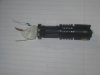
I am looking for ideas for using a multi position switch on the flashlight pictured in the attachments (please ignore the tang sticking out on the side).

The switch i will probably use is a slide switch with multiple positions. This will allow me to use different resistors for various brightnesses like i had done on other flashlights. This comes in very handy because the low setting lets the light run for many hours in case of emergency.

This flashlight is different though. It is made of all metal, including the switch. The switch is one of those 'clicky' switches where you click it to light up the light. I would change that to a slide switch or some other type of switch if you have a better idea.

I am open to doing almost anything to this light, like drilling, cutting a hole in the side, etc. But i dont think i want to ruin the original switch just in case i want to put it back one day. Otherwise i could probably drill out the guts and use that with a new switch, and i'd also need a coil spring which i already have. In fact, that was the first idea i had, to drill out the switch guts and use the screw in part and a new slide switch, but as i said i dont want to ruin the switch, unless that's the only way.

But i have a feeling there are a lot of ways to do this so i thought i would ask around. I'd like to hear any ideas no matter how wild they are. In the end i'll use the one that seems the best, although that might be hard to figure out. If there is anything on the web available that would help too.

The pictures are: one with the tail switch still on, and one with it off where you can see inside the end of the light where the threads are and the battery inside, and the switch coil spring on the switch.

As you can probably figure out, flashlights are a must have in this neck of the woods, so i dont mind spending time modding this light. The other light i did probably took more time than this will as that was built from the ground up starting with just a narrow tough plastic case. That light served me well over the years (10 watt LED of course which started way back as a 1 watter, then 3 watter, then 10 watter) but it's a little too big to be carrying around and i need one to carry that has all the modes i need.

Thanks a bunch :)
 
Last edited:
Since the switch is in a small round area, maybe use a power/volume potentiometer from a little transistor radio.
 
hi Al,
Have you considered extending the length of the torch.
Say a short section of Alum tube, inner threaded at one end and outer threaded at the other, so that the extension screws into the existing body and the switch screws into the end of the extension.?
The short section of Alum tube could house the new switch mechanism.

E
 
Hi,

Clyde:
Yes that would be nice, with a MOSFET driver cause this thing draws almost 2 amps at full brightness.

I guess what i was looking for was some mechanical scheme, as to mounting the new switch and body so as to press on the negative terminal of the battery inside like with the coil spring.
I dont have a metal lathe so i cant make a nice attachment for the end and mount a switch in that, so i need other ideas.

Eric:
I dont have a metal lathe so i cant make a pipe with threads to match the light's body threads.
Thanks though.
 
That type of light has an led for a lightsource. In the front mounted behind the led is a small circuit board that provides the control for the led. Adding in a resistor to your battery supply wont actually do what you want. While I havent taken one of the pcb's apart I do own several of those lights and as the voltage lowers they pump more current out to try and keep the light level constant. This results in a sharp drop off at the end of battery life.

The circuit used inside them does vary though. I have one where its either on or off and another where short presses of the switch once on cycles between different output modes (high>low>strobe).
 
Hello there,

Thanks for the reply.

The thing is, i've tested this light already and it does in fact dim just fine with a series resistor. Maybe some dont, but this one does, my other two smaller ones do, and my big 70 watt light dims with a series resistor. I havent come across one that doesnt dim yet in fact, which does seem strange i guess.

Yes the circuits will try to compensate, but they only go so far. Once the voltage gets low enough they do dim nicely. I 'modified' one by making a pancake resistor and just stick it into the tail end before putting on the end cap. It dims nicely, but with that solution there is no way to go back to full brightness without taking the tail cap off and removing the pancake resistor and then screwing the tail cap back on. I want to avoid that even if it means drilling into the aluminum case.

I could get another light and just ream out the clicky switch, but i hate to do that. It may come to that though if i cant think of any other idea and nobody else here can either.

I thought about drilling a hole in the side and running wires out the side, but that gets tricky too because the two wires have to come between the end of the battery and the clicky switch spring. So it's a tricky thing to have to do.
One other constraint is that the battery has to still be removable without too much trouble so that it can be replaced when needed.

This isnt the only light i would like to modify either, but they are all similar in construction so this is a good reference model.
 
Hello again,

Little update...

I made a simple replacement end cap using moldable plastic. It looks funny but it screws into the end where the tail cap normally goes, and provides one connection, and that is to the negative terminal of the battery inside. There is no case terminal so the case has to be connected to via the two little hex cap bolts that hold the pocket clip onto the light body.
There is a small spring soldered to the heavy wire, and the spring contacts the negative end of the battery when the tail cap is screwed on, just like the original tail cap.

This looks kind of funny as seen in the attachment, but it is just for doing a little experimenting while i look for a small high current switch (2amp rating at least).

Right now the large wire in the center is the negative battery wire, 16 gauge (AWG), and shorting the thin wire from one of the bolts to this wire allows the light to run at full brightness, and shorting the tiny resistor lead to the heavy wire allows the light to run at much reduced brightness with very long run time.
The switch will have to be a three position switch (or better) that connects either the thin wire or the resistor to the heavy wire, and also has an 'off' position.
I've done this with other lights like a home made one with thick plastic body, but the current for this light is much higher about 1.7 amps on full brightness, so i cant use the tiny switches i bought previously.

The down side is the light will become longer once a switch is mounted, unless i mount the switch to the side of the body and run wires through the end cap, and make the end cap shorter. Thanks to the moldable plastic it's not hard to modify the home made end cap. Mounting the switch to the side is not as simple as it sounds either because there has to be a way to stop the switch from turning 'on' when you slide it into your pocket (the intended home for this light).
The way i handled this on another light was to put the switch into the front of the light, where there was a recess so the switch could not get flicked unless you poked your finger into the front and flicked it on purpose. This worked for years. But this light will be more compact. Maybe build up a very small box to house the switch where the switch handle is recessed (a slide switch of course).

The pic is funny but it's just for the initial experiments to see how well the light will function for various purposes before committing to a full modification.
 

Attachments

  • FlashlightMod-01.jpg
    FlashlightMod-01.jpg
    78.7 KB · Views: 146
Status
Not open for further replies.

New Articles From Microcontroller Tips

Back
Top