Continue to Site

Welcome to our site!

Electro Tech is an online community (with over 170,000 members) who enjoy talking about and building electronic circuits, projects and gadgets. To participate you need to register. Registration is free. Click here to register now.

  • Welcome to our site! Electro Tech is an online community (with over 170,000 members) who enjoy talking about and building electronic circuits, projects and gadgets. To participate you need to register. Registration is free. Click here to register now.

Circuit board for flashlight - need help

Status
Not open for further replies.

makowka

New Member
Hello to all board members

May name is Simon. I would like to built a head-flashlight witch such bulbs:

https://www.conrad.pl/Żarówka-wskaź...mm,-przejrzysta.htm?websale7=conrad&pi=720183

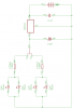
Supply 3,5V, 200mA. I would like power it through 3 AAA batteries (3x1,2V), connected in parallel. The batteries would be rechargable ones, so I think, there is a need for additional components to stabilize the power supply. I want to apply two red and two green lights, so there must be a possibility to switch between the two groups of lights, turning the whole thing off and on. I have no idea of electronics, but know some fundamental laws. Could someone please help me to design a circuit for such a flashlight?
 
For one thing, your batteries would have to be in series, not parallel... three in parallel would give you longer current draw, but at only 1.5V.

A fresh battery would be at 1.5V, 1.2V is what they read when they are nearly discharged. I actually just checked 4 AAA batteries I took out of my phone yesterday because the display was faded to be unreadable, and they all read 1.512V after sitting for a day. OK, the AA's I took out of my calculator (again, faded display, unreadable) read 1.01V.

In the charger circuit below, if you put the batteries in low, they will only charge up to 3.4V, but will trickle charge to 4v if the lamps are off. The lamps should (should) be able to handle 4v from a battery. Q2 will limit the current to 200mA.

charger.JPG
 
For the switching, a DPDT center off switch, like the 100SP3T4B1M1QEH from Eswitch (avail from digikey, pn EG2385-ND, $2.49 single qtys) should do it.

CHARGER_2.JPG
 
Hi Mike

Another question, on the picture you will see two places for the connection of the + and - from the battery pack. Can the minus connection (the upper one) be in that place? I mean, it is directly on the capacitor connection line.
 

Attachments

  • 2.png
    2.png
    577.9 KB · Views: 142
Last edited:
I'm not sure what I'm looking at here... But as long as the (-) and the capacitor are tied together... then it's ok
 
I mean, don't I have to put the battery connection on some extension, maybe in the next hole in the board (to the left)? I mean, the wire will connect to the pad on the lower side.
 

Attachments

  • 3.png
    3.png
    593.4 KB · Views: 154
  • circuit1.png
    circuit1.png
    8.1 KB · Views: 126
no, you don't have to... I tie leads together all the time when making board mods... it is probably best to, but it is up to you. As long as they're tied together in your schematic, you can put them together any way you like. Just remember you might have to take them apart also, someday.
 
OK, that is good to know, because I have little space on my board (that circle shows the border). So I can go with that layout. Thank you.
 
I wanted to use the TO-92 package, because it has not so many connections, easier to solder, too (through hole, not SMD).. LE33CZ LDO regulator, I want to employ it in order to drive the LEDs from 1,2V as well as 1,5V AAA's (variable input voltage).
 
Status
Not open for further replies.

Latest threads

New Articles From Microcontroller Tips

Back
Top