Continue to Site

Welcome to our site!

Electro Tech is an online community (with over 170,000 members) who enjoy talking about and building electronic circuits, projects and gadgets. To participate you need to register. Registration is free. Click here to register now.

  • Welcome to our site! Electro Tech is an online community (with over 170,000 members) who enjoy talking about and building electronic circuits, projects and gadgets. To participate you need to register. Registration is free. Click here to register now.

Two 7-seg Up-down counter with two switches

Status
Not open for further replies.

htunlinkyaw1807

New Member
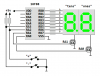
I am beginner in PIC Microcontroller....I m studying this subject and making a project which contains two 7-seg display and two switches.....project is that ..... if pressed a buttom once , one digit is up, and ...if pressed another butoom is presed , one digit is down.....but i ve many problem making this project......so can anyone help me showing one example project......thz to all
 

Attachments

  • 7seg7.asm
    4.4 KB · Views: 1,566
  • 0 to 99 UP_down counter with two switches.zip
    14.2 KB · Views: 2,467
  • 7seg7.zip
    645 bytes · Views: 1,424
Last edited:
Best to break the project up into pieces.

(1) Figure out how to read the switch and do something simple like light an LED.

(2) Next, figure out how to increment or decrement a number in memory when the switches are pressed (perhaps you can print the two numbers out through a debug connector... I'm no PIC guy so I don't know if this is possible ... or use a simulator to make sure it works).

(3) Then, figure out how to light the display properly -- the problem is each 7-segment LED takes, obviously 7 output lines... you might find that the MCU doesn't have 14 spare lines to drive the LED directly. Instead, you might need to use a BCD to 7-segment driver chip for each one, thus you'd need 3 data pins for each segment. Another option is, instead of using a 7-segment, you could use an LCD module that takes serial out from the MCU.

Does that help you get started -- or help you ask a more specific question?
 
2 7seg displays? I hope that you're either using an I/O-rich PIC with lots of pins (the 16F877A comes to mind) or you're going to use shift registers to expand your outputs (though this may require a little more code, it'll allow you to have more outputs on a low-pincount device). For the most simplicity, you'll also want to use software switch debouncing, which consists of making the micro read when the switch is pressed, wait a short time, then perform the action.

Might also be important to make sure your PIC can source enough current to drive the LEDs. If they require too much power, you may require some non-inverting buffers/drivers. If you used shift registers, this may not be a problem, since the power would be sourced from the registers instead of the PIC, assuming THEY can handle the power demand.

Hope that helps.
 
-- the problem is each 7-segment LED takes, obviously 7 output lines... you might find that the MCU doesn't have 14 spare lines to drive the LED directly...
2 7seg displays? I hope that you're either using an I/O-rich PIC with lots of pins (the 16F877A comes to mind) or you're going to use shift registers to expand your outputs (though this may require a little more code, it'll allow you to have more outputs on a low-pincount device).

OP might be multiplexing the displays to reduce I/O pin requirements. Using "direct drive" from I/O pins could provide about 20 ma 'peak' current or about 10 ma 'average' current to each display segment at a 50% duty cycle which should be pretty bright.

2-digit-up-down-png.30263


Hundreds of ways to do the software. OP might consider using one big isochronous loop or perhaps use an ISR (interrupt service routine) to refresh the displays as a background task.

I'm surprised OP couldn't find any 2-digit 7-segment up/down counter examples on the Internet.

Kind regards, Mike

<added>

A quickly thrown together (untested) isochronous loop program example;

Code:
;******************************************************************
;  2-Digit Up/Dn Counter, Isochronous Loop Example                *
;******************************************************************

        processor PIC16F88
        include "p16f88.inc"
        errorlevel -302

        __CONFIG  _CONFIG1, _LVP_OFF&_PWRTE_ON&_WDT_OFF&_INTRC_IO
        __CONFIG  _CONFIG2, _IESO_OFF & _FCMEN_OFF

ones    equ     0x20            ; 0..9
tens    equ     0x21            ; 0..9
number  equ     0x22            ; 00..99
swlatch equ     0x23            ; switch state latch variable
DelayHi equ     0x24            ; DelayCy() subsystem variable

#define DnSw    3               ; RA3

;******************************************************************
;
;  K8LH DelayCy() subsystem macro generates four instructions
;
        radix   dec
clock   equ     8               ; clock frequency in Megahertz
usecs   equ     clock/4         ; cycles/microsecond multiplier
msecs   equ     usecs*1000      ; cycles/millisecond multiplier

DelayCy macro   delay           ; 11..327690 cycle range
        movlw   high((delay-11)/5)+1
        movwf   DelayHi
        movlw   low ((delay-11)/5)
        call    uDelay-((delay-11)%5)
        endm

;******************************************************************
;
;  init hardware and program variables
;
        org     0x000
Init
        bsf     STATUS,RP0      ; bank 1                          |B1
        movlw   b'01110000'     ;                                 |B1
        movwf   OSCCON          ; select 8-MHz INTOSC clock       |B1
Stable  btfss   OSCCON,IOFS     ; INTOSC Freq Stable bit set?     |B1
        goto    Stable          ; no, branch, else                |B1
        clrf    ANSEL           ; setup PORT A for digital I/O    |B1
        movlw   b'00001100'     ;                                 |B1
        movwf   TRISA           ; RA3-RA2 inputs, others outputs  |B1
        clrf    TRISB           ; portb all outputs               |B1
        bcf     STATUS,RP0      ; bank 0                          |B0
        clrf    PORTB           ; clear portb output latches      |B0
        movlw   b'00000001'     ; digit select bits (RA1-RA0)     |B0
        movwf   PORTA           ; select the 'ones' display       |B0
        clrf    swlatch         ; clear switch state latch        |B0
        clrf    ones            ; clear 'ones'                    |B0
        clrf    tens            ; clear 'tens'                    |B0
        clrf    number          ; number = 00                     |B0
;
;  isochronous 8 msec main program loop (62.5 Hz refresh rate)
;
Main    clrf    PORTB           ; blank the display               |B0
        movf    PORTA,W         ;                                 |B0
        xorlw   b'00000011'     ; flip digit select bits          |B0
        movwf   PORTA           ;                                 |B0
        movf    tens,W          ; WREG = tens, 0..9               |B0
        btfss   PORTA,1         ; display tens? yes, skip, else   |B0
        movf    ones,W          ; WREG = ones, 0..9               |B0
        call    segtbl          ; get segment data                |B0
        movwf   PORTB           ; display new digit               |B0
TstSw   comf    PORTA,W         ; sample active low switches      |B0
        andlw   b'00001100'     ; on RA3 and RA2 pins             |B0
        xorwf   swlatch,W       ; changes (press or release)      |B0
        xorwf   swlatch,F       ; update switch state latch       |B0
        andwf   swlatch,W       ; filter out "new release" bits   |B0
        bnz     Bump            ; branch on a "new press", else   |B0
        DelayCy(8*msecs-23)     ; precise 8 msec loop timing      |B0
        goto    Main            ;                                 |B0
;
;  bump 'number' up or down with limit checking
;
Bump    andlw   1<<DnSw         ; the "Dn" switch?                |B0
        skpz                    ; no, skip (WREG=0), else         |B0
        movlw   -2              ; WREG = -2 (dn)                  |B0
        addlw   1               ; WREG = 1 (up) or -1 (dn)        |B0
        addwf   number,F        ; number++ or number--            |B0
        movf    number,W        ; WREG = number = -1..100         |B0
        xorlw   100             ; test upper limit                |B0
        skpnz                   ; upper limit? no, skip, else     |B0
        decf    number,F        ; reset to 99                     |B0
        btfsc   number,7        ; lower limit? no, skip, else     |B0
        incf    number,F        ; reset to 00                     |B0
        movf    number,W        ; WREG = number = 00..99          |B0
;
;  setup 'tens' and 'ones' for next loop
;
        clrf    tens            ; isochronous bin2bcd routine     |B0
        addlw   -80             ; W = W - 80                      |B0
        rlf     tens,F          ; shift in 2^3*10 bit             |B0
        btfss   tens,0          ; borrow? no, skip, else          |B0
        addlw   80              ; W = W + 80                      |B0
        addlw   -40             ; W = W - 40                      |B0
        rlf     tens,F          ; shift in 2^2*10 bit             |B0
        btfss   tens,0          ; borrow? no, skip, else          |B0
        addlw   40              ; W = W + 40                      |B0
        addlw   -20             ; W = W - 20                      |B0
        rlf     tens,F          ; shift in 2^1*10 bit             |B0
        btfss   tens,0          ; borrow? no, skip, else          |B0
        addlw   20              ; W = W + 20                      |B0
        addlw   -10             ; W = W - 10, now W = "ones"      |B0
        rlf     tens,F          ; shift in 2^0*10 bit             |B0
        btfss   tens,0          ; borrow? no, skip, else          |B0
        addlw   10              ; W = W + 10, now W = "ones"      |B0
        movwf   ones            ; save "ones"                     |B0
        DelayCy(8*msecs-54)     ; precise 8 msec loop timing      |B0
        goto    Main            ;                                 |B0
;
;  segment data table (caveat, non-boundary tolerant)
;
segtbl
        addwf   PCL,F           ;                                 |B0
        dt      b'00111111'     ; "0"   -|-|F|E|D|C|B|A           |B0
        dt      b'00000110'     ; "1"   -|-|-|-|-|C|B|-           |B0
        dt      b'01011011'     ; "2"   -|G|-|E|D|-|B|A           |B0
        dt      b'01001111'     ; "3"   -|G|-|-|D|C|B|A           |B0
        dt      b'01100110'     ; "4"   -|G|F|-|-|C|B|-           |B0
        dt      b'01101101'     ; "5"   -|G|F|-|D|C|-|A           |B0
        dt      b'01111101'     ; "6"   -|G|F|E|D|C|-|A           |B0
        dt      b'00000111'     ; "7"   -|-|-|-|-|C|B|A           |B0
        dt      b'01111111'     ; "8"   -|G|F|E|D|C|B|A           |B0
        dt      b'01101111'     ; "9"   -|G|F|-|D|C|B|A           |B0
;
;  K8LH DelayCy() subsystem 16-bit timing subroutine
;
        nop                     ; entry for (delay-11)%5 == 4     |B0
        nop                     ; entry for (delay-11)%5 == 3     |B0
        nop                     ; entry for (delay-11)%5 == 2     |B0
        nop                     ; entry for (delay-11)%5 == 1     |B0
uDelay  addlw   -1              ; subtract "loop" cycle time      |B0
        skpc                    ; borrow? no, skip, else          |B0
        decfsz  DelayHi,F       ; done?  yes, skip, else          |B0
        goto    uDelay          ; do another loop                 |B0
        return                  ;                                 |B0

        end
 

Attachments

  • 2 digit up-down.PNG
    2 digit up-down.PNG
    19 KB · Views: 19,569
Last edited:
Mike, K8LH You may be a brilliant programmer but you are presenting your program to a beginner and he has absolutely no possibility of understanding how some of the instructions work.

That's the difference between you and me.
I have been a teacher for 30 years and I offer the simplest approach to everything in the electronics field and that way beginners can be introduced to the subject.
If you expect a beginner to understand what you have done, you are sorely mistaken. Your program should have been much simpler in content with each instruction clearly explained.

The first thing I will suggest to the OP is this: "Do not include one single line of code that you don't fully understand."
How far do you think he will get with your brilliant coding?
 
Last edited:
Hi Colin,

I apologize if my post offended you. Please consider that while I may be showing off my programming skills I'm also sincerely interested in trying to help others by passing along my knowledge and experience.

I agree that a "good example" without careful explanation may not be very useful to a newcomer. Still, many of us learn by studying examples, good and bad, and I suspect there may be others besides the OP reading this thread who might benefit from the example I provided.

I would be happy to answer any questions the OP or other Forum members have about the example program.

If you have time, please tell me how you think I could improve that example program, short of writing a full fledged tutorial?

Kind regards, Mike
 
Last edited:
Your program did not offend me, I just think it is wise to make things easy to understand, if you want someone to latch on to a concept.
That's the difference between a University and a Technical College.
In your program, the Boolean expressions are very complex to understand as each has an “understanding within itself.” This is already a "second level" of understanding.
Then we have your decimal to BCD “concept.” This is a “third level” of understanding.
In other words, a person would have to read a whole chapter on the concept of changing decimal to BCD to understand how it works in just a few lines of code.
Don’t you realise a brilliant mathematician has devised this concept, and you are using it as a “tool.”
The same applies to your detecting and debouncing of the keys.
But it is not up to me to make these comments. I want the original poster to comment on the complexity of the program - but then he may not know it has been presented in a complex way and just “give up.”
He really needs to know the program can be produced using just the 35 PIC instructions and not even using any of the “alternate” instructions.
As I said, you have used more than 4 levels of complexity and no beginner is going to be able to comprehend a program with amount of complexity.
If you want to write a program for advanced programmers, go to the PIC forum and add your coding to the “code snippets” section where they show how to perform miracle operations in a few lines of code.
Even starting your program with the words: "Isochronous Loop Example" will leave half the beginners running for a dictionary. (Isochronous - occuring at equal time intervals). Simple putting "8mS loop" would have been sufficient.
 
Last edited:
Mike, K8LH post all the code you want the more showing off the better Ive learned a lot from your work
35 PIC instructions and not even using any of the “alternate” instructions.
I don't think he used over 35 commands there. And I hate it when
some one writes It's only 35 it takes a lot more to write good code then just them 35 commands. If some one gives up and quits they don't want to learn any way. You can almost read his code with out any comments. I love Assembly I'm no where at Mike level but if I can read it and see how it works. I no that some one that wants to learn can to.
 
Last edited:
Mike, K8LH post all the code you want the more showing off the better Ive learned a lot from your work

I agree. Please keep posting your ideas/code. I enjoy studying them.

The binary to BCD code is clever, but it doesn't take a genius to understand. A person of reasonable intelligence can understand it, if they take the time to study it. It is worth the effort.
 
I apologize if my post offended you. Please consider that while I may be showing off my programming skills I'm also sincerely interested in trying to help others by passing along my knowledge and experience.

IMHO Mike there is no need to apologise to anyone regarding the quality of your posts, especially to this self styled 'teacher'.

I find your posts interesting and informative, please dont change your style.:)

Regards
 
You will notice that not one single reply has been received by the original poster: "htunlinkyaw1807."
 
No. I think if you come in at the level of the poster, you would get a response.
I have been a teacher of electronics for over 30 years and no-one wants to know how clever YOU are.
They just want to be handed and guided in the simplest way. If they were "university material," they would not lower-themselves-down in the first place and ask for advice.
Even if the request is for homework, who are we to decide if the information is to be provided or not?
If you run down this thread for instance, you will see how the replies have gradually wandered off the topic and no-one has provided a reply that conforms with the original request.
He says: "I am beginner in PIC Microcontroller programming."
Where has he been helped?
 
Mike K8LH Your code works like butter slick. I just slapped it on the bread board and tried it Great work. The leds have good output and it counts the up and down presses.
Collins55
If he didn't learn any thing I did And I'm thankfully for it. Most of what I have learned has been from this form and people like Pommie, Mike,K8LH,3v0,Nigel,blueroom And your good site lots of goodies there. But most people learn by seeing then doing. We wouldn't have the net today if it wasn't for people
wanting to know more. It's up to the one that want's to learn. I'm not a programmer I want to be. In my 45 years I have learn a lot by just seeing how it works and if all I had was code that didn't work how would I have learned any thing. Oh that didn't work maybe next time Ha ha. How about this I see said the bind man now I see how it works let me go back and fix what I was working on. I saw the light. What better way to learn then seeing.
 
Last edited:
OP might be multiplexing the displays to reduce I/O pin requirements. Using "direct drive" from I/O pins could provide about 20 ma 'peak' current or about 10 ma 'average' current to each display segment at a 50% duty cycle which should be pretty bright.

2-digit-up-down-png.30263


Hundreds of ways to do the software. OP might consider using one big isochronous loop or perhaps use an ISR (interrupt service routine) to refresh the displays as a background task.

I'm surprised OP couldn't find any 2-digit 7-segment up/down counter examples on the Internet.

Kind regards, Mike

<added>

A quickly thrown together (untested) isochronous loop program example;

Code:
;******************************************************************
;  2-Digit Up/Dn Counter, Isochronous Loop Example                *
;******************************************************************

        processor PIC16F88
        include "p16f88.inc"
        errorlevel -302

        __CONFIG  _CONFIG1, _LVP_OFF&_PWRTE_ON&_WDT_OFF&_INTRC_IO
        __CONFIG  _CONFIG2, _IESO_OFF & _FCMEN_OFF

ones    equ     0x20            ; 0..9
tens    equ     0x21            ; 0..9
number  equ     0x22            ; 00..99
swlatch equ     0x23            ; switch state latch variable
DelayHi equ     0x24            ; DelayCy() subsystem variable

#define DnSw    3               ; RA3

;******************************************************************
;
;  K8LH DelayCy() subsystem macro generates four instructions
;
        radix   dec
clock   equ     8               ; clock frequency in Megahertz
usecs   equ     clock/4         ; cycles/microsecond multiplier
msecs   equ     usecs*1000      ; cycles/millisecond multiplier

DelayCy macro   delay           ; 11..327690 cycle range
        movlw   high((delay-11)/5)+1
        movwf   DelayHi
        movlw   low ((delay-11)/5)
        call    uDelay-((delay-11)%5)
        endm

;******************************************************************
;
;  init hardware and program variables
;
        org     0x000
Init
        bsf     STATUS,RP0      ; bank 1                          |B1
        movlw   b'01110000'     ;                                 |B1
        movwf   OSCCON          ; select 8-MHz INTOSC clock       |B1
Stable  btfss   OSCCON,IOFS     ; INTOSC Freq Stable bit set?     |B1
        goto    Stable          ; no, branch, else                |B1
        clrf    ANSEL           ; setup PORT A for digital I/O    |B1
        movlw   b'00001100'     ;                                 |B1
        movwf   TRISA           ; RA3-RA2 inputs, others outputs  |B1
        clrf    TRISB           ; portb all outputs               |B1
        bcf     STATUS,RP0      ; bank 0                          |B0
        clrf    PORTB           ; clear portb output latches      |B0
        movlw   b'00000001'     ; digit select bits (RA1-RA0)     |B0
        movwf   PORTA           ; select the 'ones' display       |B0
        clrf    swlatch         ; clear switch state latch        |B0
        clrf    ones            ; clear 'ones'                    |B0
        clrf    tens            ; clear 'tens'                    |B0
        clrf    number          ; number = 00                     |B0
;
;  isochronous 8 msec main program loop (62.5 Hz refresh rate)
;
Main    clrf    PORTB           ; blank the display               |B0
        movf    PORTA,W         ;                                 |B0
        xorlw   b'00000011'     ; flip digit select bits          |B0
        movwf   PORTA           ;                                 |B0
        movf    tens,W          ; WREG = tens, 0..9               |B0
        btfss   PORTA,1         ; display tens? yes, skip, else   |B0
        movf    ones,W          ; WREG = ones, 0..9               |B0
        call    segtbl          ; get segment data                |B0
        movwf   PORTB           ; display new digit               |B0
TstSw   comf    PORTA,W         ; sample active low switches      |B0
        andlw   b'00001100'     ; on RA3 and RA2 pins             |B0
        xorwf   swlatch,W       ; changes (press or release)      |B0
        xorwf   swlatch,F       ; update switch state latch       |B0
        andwf   swlatch,W       ; filter out "new release" bits   |B0
        bnz     Bump            ; branch on a "new press", else   |B0
        DelayCy(8*msecs-23)     ; precise 8 msec loop timing      |B0
        goto    Main            ;                                 |B0
;
;  bump 'number' up or down with limit checking
;
Bump    andlw   1<<DnSw         ; the "Dn" switch?                |B0
        skpz                    ; no, skip (WREG=0), else         |B0
        movlw   -2              ; WREG = -2 (dn)                  |B0
        addlw   1               ; WREG = 1 (up) or -1 (dn)        |B0
        addwf   number,F        ; number++ or number--            |B0
        movf    number,W        ; WREG = number = -1..100         |B0
        xorlw   100             ; test upper limit                |B0
        skpnz                   ; upper limit? no, skip, else     |B0
        decf    number,F        ; reset to 99                     |B0
        btfsc   number,7        ; lower limit? no, skip, else     |B0
        incf    number,F        ; reset to 00                     |B0
        movf    number,W        ; WREG = number = 00..99          |B0
;
;  setup 'tens' and 'ones' for next loop
;
        clrf    tens            ; isochronous bin2bcd routine     |B0
        addlw   -80             ; W = W - 80                      |B0
        rlf     tens,F          ; shift in 2^3*10 bit             |B0
        btfss   tens,0          ; borrow? no, skip, else          |B0
        addlw   80              ; W = W + 80                      |B0
        addlw   -40             ; W = W - 40                      |B0
        rlf     tens,F          ; shift in 2^2*10 bit             |B0
        btfss   tens,0          ; borrow? no, skip, else          |B0
        addlw   40              ; W = W + 40                      |B0
        addlw   -20             ; W = W - 20                      |B0
        rlf     tens,F          ; shift in 2^1*10 bit             |B0
        btfss   tens,0          ; borrow? no, skip, else          |B0
        addlw   20              ; W = W + 20                      |B0
        addlw   -10             ; W = W - 10, now W = "ones"      |B0
        rlf     tens,F          ; shift in 2^0*10 bit             |B0
        btfss   tens,0          ; borrow? no, skip, else          |B0
        addlw   10              ; W = W + 10, now W = "ones"      |B0
        movwf   ones            ; save "ones"                     |B0
        DelayCy(8*msecs-54)     ; precise 8 msec loop timing      |B0
        goto    Main            ;                                 |B0
;
;  segment data table (caveat, non-boundary tolerant)
;
segtbl
        addwf   PCL,F           ;                                 |B0
        dt      b'00111111'     ; "0"   -|-|F|E|D|C|B|A           |B0
        dt      b'00000110'     ; "1"   -|-|-|-|-|C|B|-           |B0
        dt      b'01011011'     ; "2"   -|G|-|E|D|-|B|A           |B0
        dt      b'01001111'     ; "3"   -|G|-|-|D|C|B|A           |B0
        dt      b'01100110'     ; "4"   -|G|F|-|-|C|B|-           |B0
        dt      b'01101101'     ; "5"   -|G|F|-|D|C|-|A           |B0
        dt      b'01111101'     ; "6"   -|G|F|E|D|C|-|A           |B0
        dt      b'00000111'     ; "7"   -|-|-|-|-|C|B|A           |B0
        dt      b'01111111'     ; "8"   -|G|F|E|D|C|B|A           |B0
        dt      b'01101111'     ; "9"   -|G|F|-|D|C|B|A           |B0
;
;  K8LH DelayCy() subsystem 16-bit timing subroutine
;
        nop                     ; entry for (delay-11)%5 == 4     |B0
        nop                     ; entry for (delay-11)%5 == 3     |B0
        nop                     ; entry for (delay-11)%5 == 2     |B0
        nop                     ; entry for (delay-11)%5 == 1     |B0
uDelay  addlw   -1              ; subtract "loop" cycle time      |B0
        skpc                    ; borrow? no, skip, else          |B0
        decfsz  DelayHi,F       ; done?  yes, skip, else          |B0
        goto    uDelay          ; do another loop                 |B0
        return                  ;                                 |B0

        end
thank you .....i really thank you......i can't understand the whole program ....but i can sample somethings from it ......so really thz you.....again , please advise me to improve my program i posted above....i write this program myself.....but i think i need something more in this program.....i posted asm file , HEX file, and design file of my program....i made ckt design with Protesus 6 Professional Software.... so please look at my project and edit it.....
.............................................................thank you
 
There are a few things you can do to help us help you;

(1) provide a schematic in 'png' (preferred) or 'jpg' format.
(2) declare and name your variables. you seem to be using 0x0F, 0x1A, and 0x1F but these are SFR's (special function registers) not GPR's (general purpose registers) on your 16F628A.
(3) use a meaningful __config line (look in the 16F628A "include" file).
(4) use meaningful labels and comments in your source file, for example;

Code:
setup    bsf     STATUS,RP0      ; bank 1
         movlw   03              ;
         movwf   TRISA           ; RA7:RA2 outputs, RA1:RA0 inputs
         clrf    TRISB           ; RB7:RB0 outputs
         bcf     STATUS,RP0      ; bank 0
         clrf    TMR1H           ; ??? are you trying to use 0x0F as a variable?
         clrf    CMCON           ; ??? are you trying to use 0x1F as a variable?
         goto    test            ;
Have you studied any PIC tutorials?

Regards, Mike
 
Last edited:
are you trying to set the 16f628a to digital if so all you need to do is
Code:
        movlw	0x07
        movwf	CMCON   ; turns of the comparator so you can use porta as digital
 
Status
Not open for further replies.

Latest threads

New Articles From Microcontroller Tips

Back
Top