Continue to Site

Welcome to our site!

Electro Tech is an online community (with over 170,000 members) who enjoy talking about and building electronic circuits, projects and gadgets. To participate you need to register. Registration is free. Click here to register now.

  • Welcome to our site! Electro Tech is an online community (with over 170,000 members) who enjoy talking about and building electronic circuits, projects and gadgets. To participate you need to register. Registration is free. Click here to register now.

Can u help me with this counter!!! (PIC18F46K22)

thewiseishere

New Member
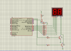
Hey guys i've been tryna build this 0-99 counter but i couldn't manage it. Can u help me out with it??
led2.4.png

C:
#pragma config FOSC = INTIO67   // Oscillator Selection bits (Internal oscillator block)
#pragma config PLLCFG = OFF     // 4X PLL Enable (Oscillator used directly)
#pragma config PRICLKEN = ON    // Primary clock enable bit (Primary clock is always enabled)
#pragma config FCMEN = OFF      // Fail-Safe Clock Monitor Enable bit (Fail-Safe Clock Monitor disabled)
#pragma config IESO = OFF       // Internal/External Oscillator Switchover bit (Oscillator Switchover mode disabled)

// CONFIG2L
#pragma config PWRTEN = OFF     // Power-up Timer Enable bit (Power up timer disabled)
#pragma config BOREN = OFF      // Brown-out Reset Enable bits (Brown-out Reset disabled in hardware and software)
#pragma config BORV = 190       // Brown Out Reset Voltage bits (VBOR set to 1.90 V nominal)

// CONFIG2H
#pragma config WDTEN = OFF      // Watchdog Timer Enable bits (Watch dog timer is always disabled. SWDTEN has no effect.)
#pragma config WDTPS = 32768    // Watchdog Timer Postscale Select bits (1:32768)

// CONFIG3H
#pragma config CCP2MX = PORTC1  // CCP2 MUX bit (CCP2 input/output is multiplexed with RC1)
#pragma config PBADEN = OFF     // PORTB A/D Enable bit (PORTB<5:0> pins are configured as digital I/O on Reset)
#pragma config CCP3MX = PORTB5  // P3A/CCP3 Mux bit (P3A/CCP3 input/output is multiplexed with RB5)
#pragma config HFOFST = ON      // HFINTOSC Fast Start-up (HFINTOSC output and ready status are not delayed by the oscillator stable status)
#pragma config T3CMX = PORTC0   // Timer3 Clock input mux bit (T3CKI is on RC0)
#pragma config P2BMX = PORTD2   // ECCP2 B output mux bit (P2B is on RD2)
#pragma config MCLRE = INTMCLR  // MCLR Pin Enable bit (RE3 input pin enabled; MCLR disabled)

// CONFIG4L
#pragma config STVREN = ON      // Stack Full/Underflow Reset Enable bit (Stack full/underflow will cause Reset)
#pragma config LVP = ON         // Single-Supply ICSP Enable bit (Single-Supply ICSP enabled if MCLRE is also 1)
#pragma config XINST = OFF      // Extended Instruction Set Enable bit (Instruction set extension and Indexed Addressing mode disabled (Legacy mode))

// CONFIG5L
#pragma config CP0 = OFF        // Code Protection Block 0 (Block 0 (000800-003FFFh) not code-protected)
#pragma config CP1 = OFF        // Code Protection Block 1 (Block 1 (004000-007FFFh) not code-protected)
#pragma config CP2 = OFF        // Code Protection Block 2 (Block 2 (008000-00BFFFh) not code-protected)
#pragma config CP3 = OFF        // Code Protection Block 3 (Block 3 (00C000-00FFFFh) not code-protected)

// CONFIG5H
#pragma config CPB = OFF        // Boot Block Code Protection bit (Boot block (000000-0007FFh) not code-protected)
#pragma config CPD = OFF        // Data EEPROM Code Protection bit (Data EEPROM not code-protected)

// CONFIG6L
#pragma config WRT0 = OFF       // Write Protection Block 0 (Block 0 (000800-003FFFh) not write-protected)
#pragma config WRT1 = OFF       // Write Protection Block 1 (Block 1 (004000-007FFFh) not write-protected)
#pragma config WRT2 = OFF       // Write Protection Block 2 (Block 2 (008000-00BFFFh) not write-protected)
#pragma config WRT3 = OFF       // Write Protection Block 3 (Block 3 (00C000-00FFFFh) not write-protected)

// CONFIG6H
#pragma config WRTC = OFF       // Configuration Register Write Protection bit (Configuration registers (300000-3000FFh) not write-protected)
#pragma config WRTB = OFF       // Boot Block Write Protection bit (Boot Block (000000-0007FFh) not write-protected)
#pragma config WRTD = OFF       // Data EEPROM Write Protection bit (Data EEPROM not write-protected)

// CONFIG7L
#pragma config EBTR0 = OFF      // Table Read Protection Block 0 (Block 0 (000800-003FFFh) not protected from table reads executed in other blocks)
#pragma config EBTR1 = OFF      // Table Read Protection Block 1 (Block 1 (004000-007FFFh) not protected from table reads executed in other blocks)
#pragma config EBTR2 = OFF      // Table Read Protection Block 2 (Block 2 (008000-00BFFFh) not protected from table reads executed in other blocks)
#pragma config EBTR3 = OFF      // Table Read Protection Block 3 (Block 3 (00C000-00FFFFh) not protected from table reads executed in other blocks)

// CONFIG7H
#pragma config EBTRB = OFF      // Boot Block Table Read Protection bit (Boot Block (000000-0007FFh) not protected from table reads executed in other blocks)

// #pragma config statements should precede project file includes.
// Use project enums instead of #define for ON and OFF.
const char cathode[10] ={0x3F, 0x06, 0x5B, 0x4F, 0x66, 0x6D, 0x7C, 0x07, 0x7F, 0x6F};
#define _XTAL_FREQ 8000000
#define display1 LATAbits.LATA0
#define display2 LATAbits.LATA1
#define button PORTAbits.RA2


#include <xc.h>

void main(void) {
    char onesplace=0, tensplace=0, number=0;
    TRISA = 0x04;
    TRISB = 0x00;
    ANSELB = 0x00;
    ANSELA =  0x00;
    PORTA = 0x00;
 
    ANSELAbits.ANSA2=0;
    display1 = 0;
    display2 = 0;
   
    while (1) {
        onesplace = number % 10;
        tensplace = number / 10;


        display2 = 1;
        display1 = 0;
        PORTB = cathode[onesplace];
        __delay_ms(5);
        display2 = 0;
        display1 = 1;
        PORTB = cathode[tensplace];
        __delay_ms(5);
        display1 = 0;

        // Check if the button is pressed
        if (button == 1) {
            __delay_ms(20); // Debounce delay
            if (button == 1) {
                number++;
                while (button == 1)
                {
                    display2 = 1;
        PORTB = cathode[onesplace];
        __delay_ms(5);
        display2 = 0;
        display1 = 1;
        PORTB = cathode[tensplace];
        __delay_ms(5);
        display1 = 0;
                }
            }
        }

        // Reset the number if it exceeds 99
        if (number > 99) {
            number = 0;
        }
    }
 
      
}
 

Attachments

  • 1720373119298.png
    1720373119298.png
    63.2 KB · Views: 129
Last edited by a moderator:
Solution
Guys i solved the problem.Problem was the resistors connected to BC337 and i changed he circuit little bit. I wanna thank to everyone who spent their the time to help solve this problem. Especially Ian Rogers to give me idea to change the circuit.

Here is new circuit and the code:
led2 son.PNG

Code:
// PIC18F46K22 Configuration Bit Settings
 
 
// 'C' source line config statements
 
 
// CONFIG1H
#pragma config FOSC = INTIO67   // Oscillator Selection bits (Internal oscillator block)
#pragma config PLLCFG = OFF     // 4X PLL Enable (Oscillator used directly)
#pragma config PRICLKEN = ON    // Primary clock enable bit (Primary clock is always enabled)
#pragma config FCMEN = OFF      // Fail-Safe Clock Monitor Enable bit (Fail-Safe...
That's too painful to read. Use the code tags to maintain the formatting of your IDE. Put the word CODE inside square brackets at the beginning and a /CODE in square brackets at the end.
 
Also, let us know what's working and not working - any compiler errors?
 
One thing you appear to be missing is a 7-segment lookup table?
eg. for each digit 0-9, the 8 bit binary or hex value that sets the appropriate segments on?

eg. a char array, so the index is the input digit and the stored data is the segment pattern.

For each digit, get the value in that array using the digit value and output that to the segments, then enable the digit for a few mS.
 
If you look at the schematic.. LATA0 is on but the transistor BC337 isn't
A) the base transistor is 4k7! and should be nearer 470 ohm ( should still give a bit of current )
B) However!! with simulation its best to use the generic NPN.

I almost always use the 2N2222a in the simulator as it tends to work nice.

Once you get the transistor to sim, it should work.
Nope, it didn't work
 
Guys i solved the problem.Problem was the resistors connected to BC337 and i changed he circuit little bit. I wanna thank to everyone who spent their the time to help solve this problem. Especially Ian Rogers to give me idea to change the circuit.

Here is new circuit and the code:
led2 son.PNG

Code:
// PIC18F46K22 Configuration Bit Settings
 
 
// 'C' source line config statements
 
 
// CONFIG1H
#pragma config FOSC = INTIO67   // Oscillator Selection bits (Internal oscillator block)
#pragma config PLLCFG = OFF     // 4X PLL Enable (Oscillator used directly)
#pragma config PRICLKEN = ON    // Primary clock enable bit (Primary clock is always enabled)
#pragma config FCMEN = OFF      // Fail-Safe Clock Monitor Enable bit (Fail-Safe Clock Monitor disabled)
#pragma config IESO = OFF       // Internal/External Oscillator Switchover bit (Oscillator Switchover mode disabled)
 
 
// CONFIG2L
#pragma config PWRTEN = OFF     // Power-up Timer Enable bit (Power up timer disabled)
#pragma config BOREN = OFF      // Brown-out Reset Enable bits (Brown-out Reset disabled in hardware and software)
#pragma config BORV = 190       // Brown Out Reset Voltage bits (VBOR set to 1.90 V nominal)
 
 
// CONFIG2H
#pragma config WDTEN = OFF      // Watchdog Timer Enable bits (Watch dog timer is always disabled. SWDTEN has no effect.)
#pragma config WDTPS = 32768    // Watchdog Timer Postscale Select bits (1:32768)
 
 
// CONFIG3H
#pragma config CCP2MX = PORTC1  // CCP2 MUX bit (CCP2 input/output is multiplexed with RC1)
#pragma config PBADEN = OFF     // PORTB A/D Enable bit (PORTB<5:0> pins are configured as digital I/O on Reset)
#pragma config CCP3MX = PORTB5  // P3A/CCP3 Mux bit (P3A/CCP3 input/output is multiplexed with RB5)
#pragma config HFOFST = ON      // HFINTOSC Fast Start-up (HFINTOSC output and ready status are not delayed by the oscillator stable status)
#pragma config T3CMX = PORTC0   // Timer3 Clock input mux bit (T3CKI is on RC0)
#pragma config P2BMX = PORTD2   // ECCP2 B output mux bit (P2B is on RD2)
#pragma config MCLRE = INTMCLR  // MCLR Pin Enable bit (RE3 input pin enabled; MCLR disabled)
 
 
// CONFIG4L
#pragma config STVREN = ON      // Stack Full/Underflow Reset Enable bit (Stack full/underflow will cause Reset)
#pragma config LVP = ON         // Single-Supply ICSP Enable bit (Single-Supply ICSP enabled if MCLRE is also 1)
#pragma config XINST = OFF      // Extended Instruction Set Enable bit (Instruction set extension and Indexed Addressing mode disabled (Legacy mode))
 
 
// CONFIG5L
#pragma config CP0 = OFF        // Code Protection Block 0 (Block 0 (000800-003FFFh) not code-protected)
#pragma config CP1 = OFF        // Code Protection Block 1 (Block 1 (004000-007FFFh) not code-protected)
#pragma config CP2 = OFF        // Code Protection Block 2 (Block 2 (008000-00BFFFh) not code-protected)
#pragma config CP3 = OFF        // Code Protection Block 3 (Block 3 (00C000-00FFFFh) not code-protected)
 
 
// CONFIG5H
#pragma config CPB = OFF        // Boot Block Code Protection bit (Boot block (000000-0007FFh) not code-protected)
#pragma config CPD = OFF        // Data EEPROM Code Protection bit (Data EEPROM not code-protected)
 
 
// CONFIG6L
#pragma config WRT0 = OFF       // Write Protection Block 0 (Block 0 (000800-003FFFh) not write-protected)
#pragma config WRT1 = OFF       // Write Protection Block 1 (Block 1 (004000-007FFFh) not write-protected)
#pragma config WRT2 = OFF       // Write Protection Block 2 (Block 2 (008000-00BFFFh) not write-protected)
#pragma config WRT3 = OFF       // Write Protection Block 3 (Block 3 (00C000-00FFFFh) not write-protected)
 
 
// CONFIG6H
#pragma config WRTC = OFF       // Configuration Register Write Protection bit (Configuration registers (300000-3000FFh) not write-protected)
#pragma config WRTB = OFF       // Boot Block Write Protection bit (Boot Block (000000-0007FFh) not write-protected)
#pragma config WRTD = OFF       // Data EEPROM Write Protection bit (Data EEPROM not write-protected)
 
 
// CONFIG7L
#pragma config EBTR0 = OFF      // Table Read Protection Block 0 (Block 0 (000800-003FFFh) not protected from table reads executed in other blocks)
#pragma config EBTR1 = OFF      // Table Read Protection Block 1 (Block 1 (004000-007FFFh) not protected from table reads executed in other blocks)
#pragma config EBTR2 = OFF      // Table Read Protection Block 2 (Block 2 (008000-00BFFFh) not protected from table reads executed in other blocks)
#pragma config EBTR3 = OFF      // Table Read Protection Block 3 (Block 3 (00C000-00FFFFh) not protected from table reads executed in other blocks)
 
 
// CONFIG7H
#pragma config EBTRB = OFF      // Boot Block Table Read Protection bit (Boot Block (000000-0007FFh) not protected from table reads executed in other blocks)
 
 
// #pragma config statements should precede project file includes.
// Use project enums instead of #define for ON and OFF.
 
 
#define _XTAL_FREQ 8000000
#define display1 LATAbits.LATA0
#define display2 LATAbits.LATA1
#define button PORTAbits.RA2


#include <xc.h>


int cathode[10] = {0x3F, 0x06, 0x5B, 0x4F, 0x66, 0x6D, 0x7C, 0x07, 0x7D, 0x6F};
int ones = 0;
int tens = 0;
int number = 0;
 
 
void main(void) {
    
    TRISA = 0x04;
    TRISB = 0x00;
    ANSELB = 0x00;
    ANSELAbits.ANSA2=0;
    DACCON0bits.DACEN = 0;
    
    display1 = 0;
    display2 = 0;
 
 
    while(1)
    {
        ones = number%10;
        tens = number/10;
        
        display2 = 1;
        LATB = cathode[ones];
        __delay_ms(5);
        display2 = 0; 
        
        display1 = 1;
        LATB = cathode[tens];
        __delay_ms(5);
        display1 = 0; 
        
      
        if (button ==1)
        {
            __delay_ms(20);
            number++;
            if (number == 100)
            {
                number = 0;
            }
        }


    }
}
 
Solution
When simulating it is best to use "digital" primitives. The 7 seg doesn't look much but using analogue resistors R1 ~ R7 will cause many simulation iterations which slows the whole thing down. You WILL need base resistors when you actually build the device ( 470 ohm) but for simulation keep it as simple as you can.


In the library look for "pullup" and "pulldown" and it will help.
 

Latest threads

New Articles From Microcontroller Tips

Back
Top