Continue to Site

Welcome to our site!

Electro Tech is an online community (with over 170,000 members) who enjoy talking about and building electronic circuits, projects and gadgets. To participate you need to register. Registration is free. Click here to register now.

  • Welcome to our site! Electro Tech is an online community (with over 170,000 members) who enjoy talking about and building electronic circuits, projects and gadgets. To participate you need to register. Registration is free. Click here to register now.

Twinkling LED Matrix Schematic Needed

Status
Not open for further replies.

mindlessmalk

New Member
Hello everyone!
I have been working with folks at electronics-lab.com and have build my very first circuit board after hundreds of back and forth messages. I think i may have burned out my resources there :(. Anyway I figure the more input i can get the better.
I am still pretty new to circuit design, though i am now able to read a schematic, and I am confident that i can put it together once i have the design... So here goes...

I need to make a circuit that will power about 30 white LEDs. I want them to turn on and off quickly (like a flash) in a random fashion, so that it creates a twinkling effect. Ideally the circuit would apply a random voltage for a random amount of time to a random LED.

I assume I will need some kind of timing IC (maybe a 555?) but it seems like there will need to be a lot more.

I would like to be able to adjust the timing in one way or another, so i will be using small pots instead of resistors in some places. I find this helps me to understand how the circuit is really working.

I have been scouring the net for any kind of schematic that would help me out. So far i am empty-handed.

Here is what i think i need:

I will have to arrange the LEDs into smaller groups.

Hopefully i can find some kind of IC that will take a single input voltage at one pin, and send an output voltage to a series of pin (perhaps 4 or 5).
The IC would control which of the 5 pins receives the output voltage, and only one of the 5 pins would receive a voltage at any given moment.

This way i could set up a group of controller ICs (maybe 6-8 of them) to control each of the 30-40 LEDs that i wil have on a board.

Using this method, only one LED from each IC could be lit at any one time, so a maximum of 6-8 LEDs will be lit simultaneously.

The part i am having trouble with is finding what type of IC would fit the bill.

I am looking for an IC that will generate a random signal to one of its (many) output pins.

Someone from the other forum told me to look into PICs, which i do not have any experience with. What type of PIC would be best suited for this job?
As usual i will continue to scour the net for anything that will help.
Any ideas? I would appreciate any nudge in the right direction.
Thanks,
Nate
 
Try searching for "multiplexing", and check out the microcontroller section of this forum. You will be able to easily control that amount of leds from a single microcontroller.
 
It sounds like a BASIC stamp might work well for this project.
I guess i am going to have to get a BASIC stamp programming part so that i can start trying some things out.

*EDIT* never mind.. i didn't realize how ridiculously expensive basic stamps were... I guess the trade off is ease of use vs. cost.

I will continue to research some cheaper PIC alternative...
 
Last edited:
Use a 40106 which can drive 6 LED's independently.
Just a cap, resistor and LED cross each gate.

Use 5 of those with different value C's and R's and problem is sorted.
 
hmmm that sounds like just what i am looking for, thanks! I will look into that! :)

*EDIT*
This appears to be the easiest and cheapest solution by far!

The chip has 6 input and 6 output pins. (along with Vdd and Vss which i believe is the same as V+ and V- or ground)

Using this chip i think i can send an input voltage to an input pin from a Cap/resistor timer and then the output pin would feed into the current limiting resistor for the individual LED.

If i replace all the timing resistors with pots then i can tune the timing of each LED. Although it would not be truly random i could stagger each "blink" to make it appears random, which is good enough for me.

(side note) Is there such a thing as a variable capacitor?

I will work on a schematic and then post it here for your review. :) Thanks!
Nate
 
Last edited:
Here is my first stab at the schematic using the 40106.

This is one part of the 5 part module that will power a total of 30 LEDs.

Do i have the connections right?

Thanks again for all your help! :D:D
Nate
 

Attachments

  • PseudoRandFlasher_v1.jpg
    PseudoRandFlasher_v1.jpg
    113.1 KB · Views: 536
mindlessmalk said:
It sounds like a BASIC stamp might work well for this project.
I guess i am going to have to get a BASIC stamp programming part so that i can start trying some things out.

*EDIT* never mind.. i didn't realize how ridiculously expensive basic stamps were... I guess the trade off is ease of use vs. cost.

I will continue to research some cheaper PIC alternative...

For less than the price of a BASIC Stamp you could get a PICkit2 or my Junebug kit ,a couple of 18Fxxx PIC and Swordfish BASIC SE.
 
Hey Bill,
You have some nice stuff on your page. Once i am (monetarily) ready to dive into PIC design I will be visiting your page again.
Thanks! :)
Nate
 
Twinkling LEDs

Hi Nate,

this is perhaps what you have been looking for. I'm already getting close to being convinced that MCUs are used more and more because of a lack of other good ideas (laziness of mind).

Use two almost identical astable mulivibrator circuits made with timer ICs. Select a high clock frequency on the clock input of a decade counter and a low clock frequency on the count inhibit input of that IC. The division of both frequencies is not supposed to deliver an even result.

That way the circuit works like a random number generator. There will one of a million of possibilities for the same pattern to repeat.

The internal logic of the CD4017 allows only one output high and all others low.

Have a look at the schematic. It's easy to make and perpaps meets your requirements. For more than ten LEDs cascade the counters. Use the carry output as a clock input for the next stage. (The carry output will also be high randomly)

Regards

Hans
 
Last edited:
Nice!
I like this approach too!
I also like that program you are using, can you tell me where to find it?
I assume the LED displays in the schematic are just for debugging purposes, and would not need to be included in the final design. Right?

In this case i could setup 3 completely separate circuits, and have them "cycling" at their own rates. That way at the most only 3 LEDs could be lit up at once. I think that would make a nice effect too.

Thanks Hans!!! :)
Nate
 
Hi Nate,

This idea is allright . . . if you add latches between the counters
and the leds.

About your circuit design Nate, it sucks, almost everything is wrong.

on1aag.
 
Hi Nate,
The CD40106 is a Cmos Schmitt-trigger input hex inverter package the same as a 74C14. The oscillator nees a capacitor to ground at its input and a resistor from its output to its input.
Its on time is almost the same as its off time unless a diode and additional resistor is added.

They will all start the same and their frequencies will be slightly different. They will look like they are each turning on and off, not random.
 

Attachments

  • Cmos Schmitt oscillator.PNG
    Cmos Schmitt oscillator.PNG
    19.2 KB · Views: 3,560
on1aag- well at least my idea is alright :p 
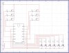
I know i need a lot of work designing schematics, and in circuit logic... but this is my second project... ever... :)

After seeing Hans' response I am thinking that may be a better route to go. I will whip up another schematic for you to laugh at :p But really, i appreciate your comments!

Hey Guru! I thought i saw your name on this site! What do you think about the decade counter approach?
 
Hi Nate,

one remark concerning my suggested circuit. If you don't want the circuit to count through 10 tie pin15 (Master Reset=MR) to the desired output. Counting through 10 might happen but might also not happen to be seen. It is an almost perfect random generator.

A reset is accomplished by taking pin15 high, which is the case if the desired count output turns high.

The program I'm using is Proteus Isis. You find it at: http://www.labcenter.co.uk. The full program is about 4.500 pounds Sterling. (approximately 11.000US$) I'm not even using half of the program's abilities. It can simulate complete MCUs and the program you intend to use with the MCU.

Debugging can be done watching the input and output pins. A high pin is coloured red and a low pin blue. If the status is indefinite the colour is grey and short circuit is indicated yellow.

I prefer using LEDs to visually control functions of circuits. They are bigger than those tiny squares indicating the status.

Regards

Hans
 
Hi Hans,
I don't think i will be buying that program anytime soon! :) but it looks pretty sweet!

Can you tell me more about the ICs you used in your sample? Specifically the last one that combines them all together. Even if you just provide a few sample part numbers i can lookup the pinouts and then i will put it together in a new schematic.
Thanks again! :)
Nate
 
Twinkling LEDs

Hi Nate,

I would like to send you the entire schematic and a layout as well. Since the files are Eagle format with suffixes .sch and .brd they are not accepted as an attachment in posts.

The board is pretty small and has only one layer with the exception of a single jumper.

Forward your email-address in a PM and you'll receive the files right away.

In the meanwhile you might want to look where to purchase NE556 and CD4017 (ST-name HCF4017). The prefixes are different depending on the manufacturer. The numeric name is unchanged.

These are the only two ICs involved in the circuits. Different from audioguru's statement you don't need many parts for a random number generator.

All you need for a complete circuit:

four resistors, five capacitors and two ICs

Regards

Hans
 
Hi hans,
your random number generator turns on one LED at random. I don't know if the time between each LED lighting will also be random.

I thought that 30 LEDs were going to be used. Wouldn't they look more random if a different quantity of them lighted each time?
 
Twinkling LEDs

Hi audioguru,

the LEDs of course stay on the same time since the 4017 is positive edge triggered. However the pattern is unpredictable because of the very much unequal frequencies of both astable multivibrators. (850Hz and 180Hz) If you just use one counter with 30 LEDs connected to 10 outputs the pattern won't look boring if the LEDs connected to same output are not mounted adjacent.

I watched the LEDs for a while and it might even happen, that 9 of 10 are omitted within one full cycle to have the same LED twinkle twice in a sequence.

I'll go one more step and try to find the best way to cascade counters, either using the highest count output to clock the next stage or use the carry out as a clock signal and probably use a separate astable for the count inhibit of each counter.

I'll tell you about the result when finished.

I already have a good idea for practical use. Mount the LEDs on the ceiling of your wife's bedroom. So she'll have twinkling "stars" even if the sky is overcast and it's raining cats and dogs. :D (Maybe it will be a good reason for divorce too. I don't know.) :)

Hans
 
LOL.. thats just about what i am trying to do! LOL

I really appreciate the back and forth too. Its helpful to see different perspectives.

I think If i set this circuit up I will have it power a set of 10 LEDs, and setup 2 completely separate circuits for the other 20 LEDs. That way each of the 10 LEDs are random, and each set of 10 LEDs is controlled separately. The way i see it, the most LEDs that could possibly be lit at once moment is 3. And that is only if each separate circuit happens to trigger an LED at the same exact time....

as for the timing of how long each LED is lit, and how long in between each light... i will have to consider that later....

Thanks again guys! :)
Nate
 
Status
Not open for further replies.

Latest threads

Back
Top