Electro Tech is an online community (with over 170,000 members) who enjoy talking about and building electronic circuits, projects and gadgets. To participate you need to register. Registration is free. Click here to register now.
Welcome to our site! Electro Tech is an online community (with over 170,000 members) who enjoy talking about and building electronic circuits, projects and gadgets. To participate you need to register. Registration is free. Click here to register now.
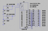
I've got one of these stars from Gooligum Electronics, it's got a tiny 8 pin PIC and 20 Charlieplexed LEDs. You'll want to use very bright LEDs as it's got a 1:20 duty for each LED. **broken link removed**
This is a really nice project. I was thinking about doing something like this as well but wasn't sure where to start. I was intending to use it for lighting in a fish tank to simulate the lighting effect you get from a pool thats inside.
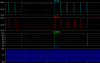
I've played a little with the circuit for more LEDs. Using the CARRY output of the preceeding stage the next counter will count in logical sequence: BACKWARDS!
Using the same high clock signal for all stages the count inhibit inputs must have different frequencies. Otherwise the same light pattern applies to every stage. The frequencies used are: 850Hz for main clock, 180Hz for the first count inhibit input and 126Hz for the second count inhibit. (126Hz due to standard value parts used).
The same main clock signal takes care of equal on time for the LEDs. With 20 LEDs the circuit already looks pretty confusing.
Trevors, I guess this circuit is just right for your application. The twinkling is very short though, but the effect will be the same as looking at water waves reflecting the sun.
Another good application idea: Carve a wooden diamond and use the LEDs on it. Your wife will love you for the hugest diamond in the world.
Can you send a full-resolution image? I am trying to reproduce your schematic in Eagle, and I think i almost have it.
I cannot seem to find the section to test the circuit out (animate it)
Hi Hans,
Instead of three 555 oscillators you could use 3 inverters from a 74C14 Cmos Schmitt-trigger hex inverter IC.
The output transistors of the CD4017 will overheat without current-limiting resistors (or just a common one) with your very high 12V supply. A 9V supply is safer and the LEDs will be almost as bright.
For 25mA output I would use 74HC4017 ICs with a common current-limiting resistor and a 6V supply. They can be clocked with a 74C14 bunch of oscillators.
It doesn't matter how much your simulator costs if your concept is
wrong. When the counters are counting the leds will be charlieplexed
and they will still light, not as bright but they will light.
I think you gonna have to make a (few) minor modification(s) to your
design.
If you add a capacitor across each LED then they will turn off fairly quickly because the output of a CD4017 goes low when the LED is turned off.
If you add a diode in seies with each LED and a capacitor across each LED then the capacitor will discharge fairly slowly into the LED without being discharged quickly when the output of the CD4017 goes low.
the caps across the LEDs won't do much. Better use low power MosFets and keep the gate voltage high long enough so the LEDs will extinguish slower. However they won't twinkle anymore.
It doesn't matter how much your simulator costs if your concept is
wrong. When the counters are counting the leds will be charlieplexed
and they will still light, not as bright but they will light.
I think you gonna have to make a (few) minor modification(s) to your
design.
the longer I look on the schematic the lesss charlieplexing I find. The LEDs will twinkle at full brightness depending on the current. As audioguru already pointed out either the LEDs or the counter will give up sooner or later with a supply voltage of 12V and no current limiting resistors.
Especially for you here is the difference between multiplexing and charlieplexing. Neither one applies to my suggested circuit.
For more info about charlieplexing visit maxim-ic.com.
Hi Hans,
Instead of three 555 oscillators you could use 3 inverters from a 74C14 Cmos Schmitt-trigger hex inverter IC.
The output transistors of the CD4017 will overheat without current-limiting resistors (or just a common one) with your very high 12V supply. A 9V supply is safer and the LEDs will be almost as bright.
For 25mA output I would use 74HC4017 ICs with a common current-limiting resistor and a 6V supply. They can be clocked with a 74C14 bunch of oscillators.
just selected the wrong power source. Should have been 9V though.
I'm not too good at math. Please tell me the difference in making the astables with 3 out of 6 inverters per circuit and using dual timers for the same purpose. My vague calculation results in three ICs in both cases.
You'll also have half of an IC leftover for general use.
This site uses cookies to help personalise content, tailor your experience and to keep you logged in if you register.
By continuing to use this site, you are consenting to our use of cookies.
")