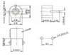
a better question is should i use a trimmer cap?
i understand that just because it is a capacitor it may not be practical in this circuit.
im just not able to get the range of fixed caps i need and looking for an alternative.
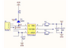
the aussie in this video has suggested i connect this in a particular way (adjusting pin to ground) so when i adjust it the metal screwdriver does not interfere with it.
View attachment 132193