ThomsCircuit
Well-Known Member
I made this circuit to help me out when im testing my swimming pools chemistry.
it agitates the water in the beaker so while i add reagent it blends it. Its a big help because its difficult to keep one eye on the beaker swirling and the other eye on the dropper and then i would need a third eye to observe the results.
How it works:
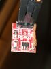
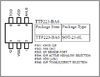
A premade ttp223 circuit is used to trip a 5V relay coil. that engages a 12V fan that has been altered. Blades removed, magnets added. When i place the beaker over the modified fan a pair of round BB style magnets reacts to the magnets beneath and rotates thus agitating the water.
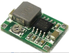
My power source is 12V. i use a buck converter to bring the voltage down to 5.4v for the TTP and the relay.
The problem:
power it up all good. touch the TTP pad and it works as expected. Touch the pad again and it turns off. Sometimes it turns back on right after i turn it off. If i touch the pad again it turns off only to turn back on as i remove my finger away from the pad. I can stop this behavior if i hold my finger over the pad for a few seconds to turn it off. So thats my work around. Hover finger for a brief time and behavior is normal.
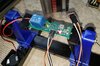
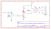
I initially had the TTP223 sensor mounted directly on the circuit board. it was next to the buck converter. When in that location the ttp would go berserk. Like a dog chasing its own tail it would (without interaction from me) toggle on and off rapidly and without pattern. I could not stop it. Since relocating it farther away from the rest of the circuit its behavior is more tame but still odd. All i can offer in my research of the TTP chip is it re calibrates itself. It may have something to do with it. I appreciate any ideas on what / why this may be happening. The schematic (pic) is just what i did with the exception of adding the buck converter and a second led. (470R resistor, red led, connected to 12v)
it agitates the water in the beaker so while i add reagent it blends it. Its a big help because its difficult to keep one eye on the beaker swirling and the other eye on the dropper and then i would need a third eye to observe the results.
How it works:
A premade ttp223 circuit is used to trip a 5V relay coil. that engages a 12V fan that has been altered. Blades removed, magnets added. When i place the beaker over the modified fan a pair of round BB style magnets reacts to the magnets beneath and rotates thus agitating the water.
My power source is 12V. i use a buck converter to bring the voltage down to 5.4v for the TTP and the relay.
The problem:
power it up all good. touch the TTP pad and it works as expected. Touch the pad again and it turns off. Sometimes it turns back on right after i turn it off. If i touch the pad again it turns off only to turn back on as i remove my finger away from the pad. I can stop this behavior if i hold my finger over the pad for a few seconds to turn it off. So thats my work around. Hover finger for a brief time and behavior is normal.
I initially had the TTP223 sensor mounted directly on the circuit board. it was next to the buck converter. When in that location the ttp would go berserk. Like a dog chasing its own tail it would (without interaction from me) toggle on and off rapidly and without pattern. I could not stop it. Since relocating it farther away from the rest of the circuit its behavior is more tame but still odd. All i can offer in my research of the TTP chip is it re calibrates itself. It may have something to do with it. I appreciate any ideas on what / why this may be happening. The schematic (pic) is just what i did with the exception of adding the buck converter and a second led. (470R resistor, red led, connected to 12v)

")