Continue to Site

Welcome to our site!

Electro Tech is an online community (with over 170,000 members) who enjoy talking about and building electronic circuits, projects and gadgets. To participate you need to register. Registration is free. Click here to register now.

  • Welcome to our site! Electro Tech is an online community (with over 170,000 members) who enjoy talking about and building electronic circuits, projects and gadgets. To participate you need to register. Registration is free. Click here to register now.

Trying 2 implement two signals analog division using hardware

Status
Not open for further replies.

Trying2

New Member
Hi guys,
I'm stuck.
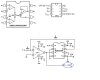
I tried using the following scheme conficurations on a breadboard, but always get a the unique ~ 14V result, without any influence of the two voltage sources:
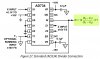
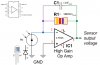
Attached are the implemntation circuits I used.

- "loads" are the same - preamped photodiodes of the same nature and with a 100KOhm feedback resistor (& parallel 0.1uF capacitor - which give bot when connected to the circuit and when sampled on their own ~ 0.2V-14V, where the 14V is only under direct ilumination, so ambient light ~ 0.2-0.5V). Maybe I need to replace with 1MOhm to producemore than 1V, but I doubt that this is the problem.

I've checked that I'm getting the +15V, -15V and "0" as source to all circuits (my "0" is also my "grd", as I don't see how this can be implemnted otherwise).
I did not opt for the "optional" configs, just a straight wiring with jumpers, necessary resistors and capacitors as suggested.

Any help in understanding why this doesn't seem to work will be greatly appreciated.

-After posting, I switched the RC photodiode feedback to 1MOhm & 1nF (SMD), and got better ambient light response - but still "no cigar"..
 

Attachments

  • AD633_V-div_#1_configs.jpg
    AD633_V-div_#1_configs.jpg
    471.1 KB · Views: 182
  • AD734_V-div_#1a_configs.jpg
    AD734_V-div_#1a_configs.jpg
    600.9 KB · Views: 182
  • AD734_V-div_#2_configs_Adjusted.jpg
    AD734_V-div_#2_configs_Adjusted.jpg
    878.4 KB · Views: 179
  • MPY634_V-div_#1_configs.jpg
    MPY634_V-div_#1_configs.jpg
    462.2 KB · Views: 192
  • Load.jpg
    Load.jpg
    277.1 KB · Views: 163
Last edited:
What are building?
Light is the input.
Voltage is the output?
Are you adjusting the gain?
 
What are building?
Light is the input.
Voltage is the output?
Are you adjusting the gain?
The Last Q is is the significant one, so..This is my way of stabilizing the work point of CW laser without complicating things.

So the task is simple - get the 10V or so from one of these components, and see that it reacts well to changes between the two PDs.

Round 12Y ago I used the same circuit implementation successfully, but I can't find my notes from then...
 
What happens if you use two potentiometers for the input voltages,so you can directly control those?
 
What happens if you use two potentiometers for the input voltages,so you can directly control those?
A CW laser, goes during "on" stage through several changes that change its work-point: temperature cycling, mode hopping (mode competition), etc..
This is not something you set "by hand" and hope for the best. Whish it were...
 
it might be helpful if we saw the actual schematic of what you have built. the schematics shown are yanked from the data sheets. also, for LEDs to work properly as sensors, they LED's output spectrum (when it's used as an LED) should include the color of the laser. a red LED would make a good sensor for a red laser, but a green or blue LED would not.
 
it might be helpful if we saw the actual schematic of what you have built. the schematics shown are yanked from the data sheets. also, for LEDs to work properly as sensors, they LED's output spectrum (when it's used as an LED) should include the color of the laser. a red LED would make a good sensor for a red laser, but a green or blue LED would not.

There are no LEDs in the circuits. The only Q is if you can see why it would behave like this, and LEDs are NEVER used as PDs.
Get your facs straight before "stepping in".
Also, a laser eint a LED.
PLEASE DO NOT WRITE THINGS FOR THE SAKE OF WRITING THEM !! -SO FAR THERE WAS NOT ONE THAT HAD A CONSTRUCTIVE AND TO THE POINT REPLY..
IF YOU DON'T KNOW, THEN YOU CAN ADMIT NOT KNOWING AND NOT TRY TO ANSWER.
 
your sensor circuit shows an LED being used as a photodiode (as a matter of fact it actually references the sensor as LED1 ) helping you with your question isn't going to be easy since you haven't posted an actual schematic of what you have. you toss out 4 examples yanked from data sheets without showing any connections you have with any sensor circuits that you have assembled. then you rant in all caps because all we can do here is guess because you haven't provided any useful information. so, sit down take a breath, calm down, and post a schematic of exactly what you are working with.
 
your sensor circuit shows an LED being used as a photodiode (as a matter of fact it actually references the sensor as LED1 ) helping you with your question isn't going to be easy since you haven't posted an actual schematic of what you have. you toss out 4 examples yanked from data sheets without showing any connections you have with any sensor circuits that you have assembled. then you rant in all caps because all we can do here is guess because you haven't provided any useful information. so, sit down take a breath, calm down, and post a schematic of exactly what you are working with.
Then Sir, you don't know a lot about the nature of LEDs vs. Photodiodes.
If you have to reשd the letters and do not understand the nature of the loads that simulate the input from the actual loads, then this discussion is not the place for you to be in.
Sorry.
PS -The load circuits work fine, so I attached them just to illustrate. The circuit, if working correctly should yield 10V for equal loads, so it is a contained problem. Anything else is irrelevant to the problem at hand.
 
Last edited:
A CW laser, goes during "on" stage through several changes that change its work-point: temperature cycling, mode hopping (mode competition), etc..
This is not something you set "by hand" and hope for the best. Whish it were...

I did not mean for controlling the laser, it's purely to be able to test the divider circuit and see what combinations of input voltages give what output voltage, to try and determine exactly what it is doing!
 
I did not mean for controlling the laser, it's purely to be able to test the divider circuit and see what combinations of input voltages give what output voltage, to try and determine exactly what it is doing!
The thing is, that for roughly equal loads (provided by the two PDs) it should yield ~10V, and when you shine uppon the numerator, it should decrease, while increasing when the denominator gets more light.
If these configurations yiled 14V and are barely influenced by loads that repeatedly yield between 0.8V - 14V each, when hit by intensified light (such as shining a bright white LED closer and closer to each one), then something is not working, which in these cases is the situation.
I'm hoping that someone has the experience or just a discerning eye, that can shine a light as to what's wrong here.
I've mentioned before, that 12Y ago, I used the approximate circuit with great success, but lost my schematics...
 
Status
Not open for further replies.

Latest threads

New Articles From Microcontroller Tips

Back
Top