Continue to Site

Welcome to our site!

Electro Tech is an online community (with over 170,000 members) who enjoy talking about and building electronic circuits, projects and gadgets. To participate you need to register. Registration is free. Click here to register now.

  • Welcome to our site! Electro Tech is an online community (with over 170,000 members) who enjoy talking about and building electronic circuits, projects and gadgets. To participate you need to register. Registration is free. Click here to register now.

Trigger circuit for LED lights

Status
Not open for further replies.

MAJ

New Member
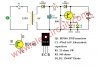
Hello, I want to build a circuit that drives a 3V series of LEDs. The LEDs turn ON when the mains power is off, and the LEDs run on a Li-ion battery (3.7V). When the mains power comes ON, the LEDs turn off, and the circuit starts charging the battery. I hope to find a simple circuit with transistors or 555/741 chips.

Thanks.
 
What you want is an emergency light, as freely available commercially, and modern ones all use LED's now.

Like this example:

**broken link removed**

Most seem to use NiCd still, not even NiMh, so presumably there are advantages in doing so?. If you google there are many simple schematics out there to look at - but for Li-Ion you need more accurate charging.
 
Thanks for your reply. This is what I want TO MAKE. I want a simple circuit that I can build and use.
 
I'd suggest looking at the circuits used in solar garden lights, then adapt for the different voltage.
Plus using a suitable regulated charger lithium cell charger instead of the solar panel.
 
A Lithium single battery cell voltage is 3V when almost dead, 3.7V when half-discharged and 4.2V when fully charged. Then the need current regulation so the brightness of the LEDs does not change. But a 3V LED barely lights up with only 3V because its current-limiting resistor or circuit needs more voltage.

The minimum supply voltage of an ordinary 555 is 4.5V but a modern Cmos 555 works fine down to 2V.
The minimum supply for an antique 741 opamp is about 10V.

So you need a mains power detection/switch, a voltage booster circuit, a current regulator circuit and a charging circuit.
 
Example circuit:
**broken link removed**

It would probably want double the turns on the coil and then run 3-4 LEDs in series if the 1.5V cell was replaced by a lithium cell.

Add a suitable current limited mains-derived power source instead of the solar panel, set to give around 4.1V at the cell when it's fully charged.
 
plug a 5v wall wart into the mains....get a 5v relay........using a series resistor, connect the relay coil to the 5v output....when the mains goes off...your relay will switch......make that switch turn on your led circuit, and your battery charger circuit.
 
plug a 5v wall wart into the mains....get a 5v relay........using a series resistor, connect the relay coil to the 5v output....when the mains goes off...your relay will switch......make that switch turn on your led circuit, and your battery charger circuit.
Thank you for the suggested method. I have used similar method before, and has been working very well. I wanted to use a simple transistor based circuit to do that, and found many circuit designs out there. I have found the circuit in the attached file, which is simple using one transistor, and I have used a transformerless circuit to obtain the 5V DC. The final circuit is small and works well.
Thanks for everyone.
 

Attachments

  • mini-emergency-light-circuit-600x395.jpg
    mini-emergency-light-circuit-600x395.jpg
    58.3 KB · Views: 242
Status
Not open for further replies.

Latest threads

New Articles From Microcontroller Tips

Back
Top