Electro Tech is an online community (with over 170,000 members) who enjoy talking about and building electronic circuits, projects and gadgets. To participate you need to register. Registration is free. Click here to register now.
Welcome to our site! Electro Tech is an online community (with over 170,000 members) who enjoy talking about and building electronic circuits, projects and gadgets. To participate you need to register. Registration is free. Click here to register now.
Eric, I am sorry to beat this old horse to death but didn't I say that copies frequently have errors? Does Fairchild hire little kids?
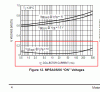
The graphs for a Motorola/ON Semi transistor has a typical saturation voltage of about 40mV but Fairchild's has more than 200mV. Fairchild's written spec's say 200mV maximum. Motorola/ON Semi says 250mV maximum.
Another saturation graph in Fairchild's datasheet shows that its saturates poorly when its collector current is 100mA and its base current is 20mA.
A Japanese company (Toshiba?) copied the Texas Instruments audio ICs the TL071 single, TL072 dual and TL074 quad opamps.
But they made them "better" with a higher frequency response.
Every one of them oscillated at a high frequency and all of them were recalled. Then they deleted the datasheet.
nah i dont mind, all info ends up useful. as for why i didnt use a single transistor i explained that near the start, i have to use what i have to hand at the moment and the npn i have handy wouldn't handle the current. and its driving a motor. another reason of course is the whole learning thingy, trying out a circuit i havnt used before and learning new things, by the time i get to uni i will hopefully be going in with a good grounding on both theory and practical. I have at least 5 years ahead where i have to learn via the pro's on here and what i can get from books.
hi agu,
The way I read that plot you posted is at Ic=100mA the Vce sat is 0.25V, with an assumed Ib=10mA, ie Beta of 10.
The point I am disputing is your earlier statement that Vce sat for the MPSA56 is 1V.
I agree errors are made in manufacturers datasheets and quite often Errata notes are published to correct them.
In post #25 I said. "The spec's for hFE show that the transistor is a linear amplifier (not a saturated switch) with a collector-emitter voltage of 1V, not 0.05V".
In post #25 I said. "The spec's for hFE show that the transistor is a linear amplifier (not a saturated switch) with a collector-emitter voltage of 1V, not 0.05V".
The maximum VCE sat is 0.25V at a collector current of 100mA. The "typical" plots show about 0.04V.
But in post #36 you wrongly say 0.2V and show Fairchild"s wrong graph that shows it.
Not only the plot shows 0.2V, so does the text extract as shown in the clip I posted from the Fairchild datasheet. [repeated here]
I also posted the plot from Motorola 's datasheet which also shows close 0.2V for Vce sat.
I would say its close enough either as 0.2V or 0.25V it does not make one bit of difference to the circuit.
I cannot understand the point you are trying to make.? it must be unnecessarily confusing to the OP.
My point is that the datasheets of THE SAME TRANSISTOR should be IDENTICAL even if the manufacturers are different.
Fairchild's graph is completely different from Motorola's and the written spec's are also different.
Hee, hee. National Semi copied Motorola's written spec of 0.25V for the maximum VCE at 100mA but copied Fairchild's graph showing a "typical" saturation voltage a little more than 0.2V.
well as the op the debate you have been having over the datasheet has been extremely useful, i originally just googled the part number and grabbed the first datasheet in the list and off i went. what i didnt know until the debate was that datasheet for the same part# could be different from each manufacture,it also never occurred to me that in a datasheet the written word could differ from the posted graph in the same sheet. Ok for what i am doing it dosnt matter, but in future if i do something that does matter i will be careful in checking the data sheet. i also think it's bad that they can publish data sheets with error's and not at some point correct it and republish the sheet, i understand that's what errata is for but surely leaving a graph that dosnt match the words in a datasheet is pretty poor. so anyway it's been educational for me.
on a different point i have updated my drawing to the following
i have added a sense resistor but would like to add a indicator LED, i have thought about it but not sure the best place to place it, i would like to keep the mA from the pic pin down as much as i can, the LED need only be run at around 10mA so where would be best in the circuit with the least inpact??
The written word on the datasheet for the MPSA56 transistor is the maximum VCE sat (0.25V at 100mA). The graph (0.04V at 100mA) is for a "typical" part but some are better and some are worse. It looks like Fairchild's graph is a mistake and is for a much weaker transistor than a powerful MPSA56 transistor.
This site uses cookies to help personalise content, tailor your experience and to keep you logged in if you register.
By continuing to use this site, you are consenting to our use of cookies.


 it must be unnecessarily confusing to the OP.

