Continue to Site

Welcome to our site!

Electro Tech is an online community (with over 170,000 members) who enjoy talking about and building electronic circuits, projects and gadgets. To participate you need to register. Registration is free. Click here to register now.

  • Welcome to our site! Electro Tech is an online community (with over 170,000 members) who enjoy talking about and building electronic circuits, projects and gadgets. To participate you need to register. Registration is free. Click here to register now.

Transistor rusty

Status
Not open for further replies.

needhelpplease

New Member
Hi all,
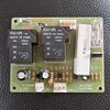
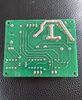
Very new to electronics. I am having a problem with the auto wire feed on my welder, I noticed the wire feed control panel has a rusty transistor ? Could this stop my controler from working and could I test it in situ on the board. If so, how please.
Thanks
 

Attachments

  • 20210505_185521.jpg
    20210505_185521.jpg
    833.6 KB · Views: 228
Sorry, I forgot to mention, when I press the trigger on the torch it should start the wire feed. It doesn't. But I can here 2 relays click.
 

Attachments

  • 20210501_115924.jpg
    20210501_115924.jpg
    890.1 KB · Views: 253
  • 20210501_115942.jpg
    20210501_115942.jpg
    1.1 MB · Views: 248
Have you checked if there is a voltage at the connections to the wire feed motor when the trigger is pressed ? I would guess that it is a low voltage ( 12 - 48 volt.) DC motor but you should be able to check it's voltage rating from the documentation that was supplied with your welder.

Les.
 
Hi Les, thanks for your answer, there is no power getting to the 24v wire feed motor so I connected a 12v battery charger straight to the motor, it worked fine.
I'm sure it's something wrong with the board. I checked the BT151 thyristor and the KSP42 transistor and they were both fine.
Any other ideas would be great and thanks again.
 
I would think the 40A relays are for enabling the welding transformer itself, not necessarily for the feed motor. What is BT151? It might be a driver transistor/MOSFET to supply some voltage to the feed motor. What are the voltage ratings on the capacitors on that board? If low voltage, they may be part of the motor voltage feed. The small "rusty" transistor could be a problem. but hard to tell if it is part of the motor feed or controls the relays. Are there any other transformers in that device? Is the fuse ok?
It would be good to know which connector is connected to the feed motor...
 
Thanks sagor1, yes there is a small transformer that connects to the PCB .
the rusty looking transistor tested fine when removed. Also the BT151 thyristor tested fine when removed.
I think your correct about the relays and I can hear them clicking when the torch trigger is pressed.
 

Attachments

  • 20210506_151025.jpg
    20210506_151025.jpg
    2.2 MB · Views: 231
Do you know how I would test the small transformer ?
Any help would be great.
Transformers like that rarely go wrong without having been overloaded, and then they will overheat and burn out.

As it's a 240/24 V transformer, the 240 V winding will have around 100 times the resistance of the the 24 V winding.

If you connect 240 V mains to the 240 V winding, you will get 24 - 30 V ac from the secondary. If not, the transformer is dead.
 
You may be able to test the small transformer with a basic multimeter, set to AC voltage readings. One would expect something in the 12 to 24VAC range if it drives a DC motor. From your picture, it shows 220V input and 24V AC output. I suspect the two blue wires are the 24V winding. Check the input voltage first, to make sure the transformer is getting power in the first place. If so, measure the secondary voltage. From there, one has to trace it on the circuit board.
Upon further review, it looks like that transformer is simply supplying the 24VDC to energize the two large relays. The motor feed seems to come from CN2. and may be related to feed from CN3. What feeds CN3?
 
Sagor1,
Thanks for that, I will check that.
Great instructions and thank you.
I will check what feeds CN3 and report back if that's OK.
 
I agree with sagor1 that the BT151 probably is involved in driving the motor. I think the small transformer only drives the relays. So if the relays that you can hear click are the two on the board in the picture then the transformer must be OK. I think the trigger switch is connected to contacts 1 and 3 (counting from the left with CN2 at the top of the picture.) that when closed connects the 24 volts AC to via D1, R1 and C1 to both relay coils which are in parallel. (The contacts on these relays are also in parallel so it can be considered as one relay.) I have not yet traced any more of the schematic but I have added a mirrored picture of the etch side of the board to make tracing it easier. If you can trace which connections on the board that the motor is connected to that would be helpful.

060421.jpg


Les
 
Les Jones, thanks for that info.
I will trace which connections on the board that the motor is connected to and report back if that's OK.
Thanks a lot for your help.
 
This is my attempt at tracing out the schematic of the board. It will mean more when the external connections have been traced.
070521.jpg


Les.
 
Thank you Les.
OK, checked a few things.
One wire from the feed motor goes to CN2 block.
All the 3 red wires from the speed pot goes to the CN3 block.
I have included 2 diagrams (don't laugh haha )
I tested the transformer for 240v and it feeds from the on switch. I did read 240v.
I tested the 2 blue wires (output) for 24v but got nothing, no reading.
I don't understand if the transformer is broken then how come when I press the trigger I can get either one or two relays clicking.
 

Attachments

  • 20210507_094716.jpg
    20210507_094716.jpg
    639.4 KB · Views: 207
  • 20210507_101219.jpg
    20210507_101219.jpg
    708.3 KB · Views: 201
I think the two relays in parallel control the mains to the big transformer. When you press the trigger check that you get an AC input the the main rectifier and a DC output from it ? Also does the solenoid valve for the gas open when the trigger is pressed ?

Les.
 
Les, I may of tested the transformer wrong?
Out of the black, yellow and red wires which ones do I connect to test 240v in. And are the blue 24v out ?
Thanks
 
Looking at the marking on your transformer it looks like it has two tapings on the primary. One for 220 volts and one for 380 volts. You have a few options. One is to trace the wiring back to the mains input. If your welder is designed only for 220 volts input then probably one of the primary wires will not be connected. If it is dual voltage (So you have the option of connecting it phase to phase on a 3 phase supply rather than phase to neutral.) you will have to see how it is connected to the voltage selection switch / links. I would first do a resistance test between all three primary wires to make sure that the primary has not failed open circuit. You could also measure the resistance of the secondary but that is unlikely to have failed open circuit.
Have you confirmed that it was the relays on the board that you could hear clicking when the trigger was pressed ? Are there any other relays or circuit boards in the welder ? Can you post a link to the manual for the welder so we have an idea about it's ratings.

Les.
 
Thank Les.
It is a Duel voltage 230v and 400v BUT the voltage know has a stop on it so you can't move it to 400v.
Defo no other relays on board. I put my ear as near as I dare and it was either one clicking or both, it's hard to tell.
But a defo click when trigger pressed.
If its ok, I will trace the wires and get back to you.
Thanks again Les, really appreciate your time and knowledge.
 
Status
Not open for further replies.

Latest threads

New Articles From Microcontroller Tips

Back
Top