Continue to Site

Welcome to our site!

Electro Tech is an online community (with over 170,000 members) who enjoy talking about and building electronic circuits, projects and gadgets. To participate you need to register. Registration is free. Click here to register now.

  • Welcome to our site! Electro Tech is an online community (with over 170,000 members) who enjoy talking about and building electronic circuits, projects and gadgets. To participate you need to register. Registration is free. Click here to register now.

Trying to fix an old tape recorder SHARP RD-418

Caninas

New Member
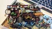
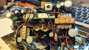
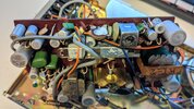
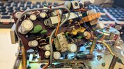
I've been trying to fix this old tape recorder in the past couple of days. I have basic knowledge on electronics, still trying to learn. The tape recorder doesn't play any audio, everything else works fine (mechanically speaking). Tested most capacitors and resistors, all of them were fine (except one), no short on the circuit. Speaker is working. No sound on EAR output too.
I narrowed the problem to somewhere around the two 2SB324 transistors (Q4 and Q5), the 2Ω R20 resistor connecting the transistor emitters was visually burnt from overheat, still working, but with higher impedance (13Ω). Replaced the resistor. Reading the voltages on the Q4/Q5 transistors pins I got:

E: slowly increasing from 0.8 volts
C: slowly dropping from 5.4 volts
B: slowly dropping from 5.25 volts

Both transistors are running really hot, to the point of burning the solid/liquid thing around them, inside the heat sink, in less than a minute running (heats faster with a cassette tape on). The resistor I replaced is also burning, probably due to the high current going into it.
Base from transistor Q3 is running at 5 volts instead of 0.8, all components around it are working as intended. Q1 and Q2 are running fine voltage wise. Don't know if it could be the transformers or transistors at fault. I'm stuck here. Don't know where to go from here

I've read this article, he also got a problem at the same kind of resistor, but replacing it didn't work for me.
https://www.electro-tech-online.com...shot-1960s-panasonic-transistor-radio.163778/

The only modification I've made is the resistor swap, all other cables are from factory (presumably)
This manual is the most i could find about this model.
(I don't think the new belt is at the correct position, but that is the only position I could think to make it work correctly)
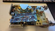
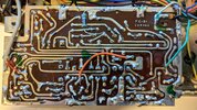
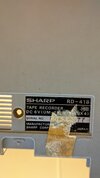
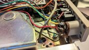
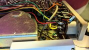
PXL_20240816_013144852.jpgPXL_20240816_013218816.jpgPXL_20240816_013421776.jpgPXL_20240816_013452832.jpgPXL_20240816_013307403.jpgPXL_20240816_013606586.jpgPXL_20240816_013714899.jpg
 

Attachments

  • SHARP RD-418 MANUAL2.pdf
    3.4 MB · Views: 63
Last edited:
OK, you don't repair things by randomly trying to test resistors and capacitors - the VAST likelihood is transistor failures, particularly in the output transistors, which then caused the emitter resistor to burn up. Just replacing burnt up resistors is highly unlikely to cure anything, you need to repair the cause of the resistor burning up.

You're also fairly vague on your voltage measurements, you don't mention where you're referencing them from?, or what polarity they are?. This is an antique design, and thus uses a positive chassis - all voltage readings are negative, with respect to the positive side of the battery (chassis).

As it's a transformer coupled amplifier, there's no DC connection (as with more modern designs), so all that will have failed is likely to be the two output transistors, and the damaged 20 ohm resistor.

I'm presuming the batteries are connected the correct way?, pin 5 of the output transformer should be positive, and all voltage readings (made with the black negative probe) should be made in respect to that. The negative of the battery should be connected to pin 2 of the output transformer.
 
Thanks for taking the time. I've been using an AC adaptor at 6 volts, center positive polarity. Didn't bother so much because where I live everything is positive polarity centered and thought this one was too, totally misread the schematic. It's all inverted. Changed the cables at the input, so plus from AC goes to circuit exterior. Probably had a proper AC adaptor but was lost.
Before/After
PXL_20240816_113109492.jpgPXL_20240816_124144492.jpg
Now voltages on all transistors are fine, red probe at pin 5 of the output transformer

E: 0.04v
C: 6.18v
B: 0.18v

All problems are gone, but still no sound. Maybe something broke because of the inverted polarity? Will swap the head to see if something changes
 
Turn the volume right up, and holding a screwdriver in your fingers (so you're touching the metal blade) apply the end of it to the top of the volume control, you should hear a buzz from the speaker every time you touch the screwdriver to it. If you do, then the fault is before the volume control, if you don't them it's after it - this is called the 'half spilt method'.

In my considerable experience (46 years doing TV etc. repairs) the polarity of those DC connectors seems pretty random, probably about 50/50 either way.
 
Thanks for taking the time. I've been using an AC adaptor at 6 volts, center positive polarity. Didn't bother so much because where I live everything is positive polarity centered and thought this one was too, totally misread the schematic. It's all inverted. Changed the cables at the input, so plus from AC goes to circuit exterior. Probably had a proper AC adaptor but was lost.
Before/After
View attachment 146712View attachment 146713
Now voltages on all transistors are fine, red probe at pin 5 of the output transformer

E: 0.04v
C: 6.18v
B: 0.18v
still no sound. Maybe something broke because of the inverted polarity? Will swap the head to see if something changes
My bet on the most likely problem is with the switches, especially if the unit has been sitting in a box for a number of years. Most likely, they used to have some kind of lubricant on the sliding contacts that has dried, and is not allowing the contacts to properly complete the circuits. A can of contact cleaner spray should clean them sufficiently to make it work.
Hit each switch with a blast of cleaner and exercise them a number of times. You can connect an ohmmeter onto each switch to monitor the continuity until they are reliable again.
Cheers,
OldTechie
 
Turn the volume right up, and holding a screwdriver in your fingers (so you're touching the metal blade) apply the end of it to the top of the volume control, you should hear a buzz from the speaker every time you touch the screwdriver to it. If you do, then the fault is before the volume control, if you don't them it's after it - this is called the 'half spilt method'.

In my considerable experience (46 years doing TV etc. repairs) the polarity of those DC connectors seems pretty random, probably about 50/50 either way.
It was before the volume control.
My bet on the most likely problem is with the switches, especially if the unit has been sitting in a box for a number of years. Most likely, they used to have some kind of lubricant on the sliding contacts that has dried, and is not allowing the contacts to properly complete the circuits. A can of contact cleaner spray should clean them sufficiently to make it work.
Hit each switch with a blast of cleaner and exercise them a number of times. You can connect an ohmmeter onto each switch to monitor the continuity until they are reliable again.
Cheers,
OldTechie
Indeed it was the switch. Had to clean it a little bit and it started playing.

But it all sound very muffled and a bit distorted, both speaker and ear out. Sounds like 80s japanese pop lofi but worse. Speed is a little slower. The tapes that I used are running fine on another tape recorder. Changed the belt to a tighter one, no changes.
A little sample (I turn the volume up at the middle (gets really loud) and then down):
 
Last edited:
With such large base-emitter voltages on them, I'd think Q3 - 4 - 5 need replacing.

They are old germanium devices, which can degrade over time even if never mistreated.

I got a batch of "new, old stock" ones to repair a bit industrial gear a couple of years ago and many had degraded to the point of being unusable.
Will be ordering new 2sb324, but still searching for Q3 2sb175, probably going to be ordering it from china. I will come back when I get them changed, for those who got here and have the same problem.

Anyway thank you all for taking the time to help me out!
 
If you cannot find the originals, you could use AC128 to replace those, they has higher ratings similar gain.

Get plenty of spares & test them for best gain and lowest leakage before using them; they are still available but decades old and a lottery as to how good or bad they are.

I got twenty and they varied from full spec to completely dead..
 

Latest threads

New Articles From Microcontroller Tips

Back
Top