Continue to Site

Welcome to our site!

Electro Tech is an online community (with over 170,000 members) who enjoy talking about and building electronic circuits, projects and gadgets. To participate you need to register. Registration is free. Click here to register now.

  • Welcome to our site! Electro Tech is an online community (with over 170,000 members) who enjoy talking about and building electronic circuits, projects and gadgets. To participate you need to register. Registration is free. Click here to register now.

Active Speaker Powers on but No Sound. Replaced transistors.

Sniper19

New Member
I have a Hybrid PB 15" Active Speaker.
It has 2 channels and a Speakon Amp out port.
The speak blew due to an electrical surge. I replaced the fuse, Replaced all 4 transistors (2x A1941 and 2x C5198) I replaced 2 R100 resisters (brown black brown gold) but still no sound.
Speaker Powers up but the Relay does not click. If I connect a audio source into the speaker the speaker does not play but if I connect another speaker to this speaker using the line out port , the connected speaker plays which means the Inputs are fine and the output line out is fine but the Speakon Amp out doesn't play or power an external speaker and the internal sub and tweeter don't play.
Capacitors don't look popped

What else can I check? Is my relay blown or is something else causing the relay not to even start up.

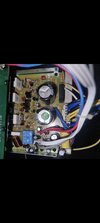
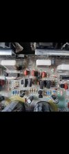
Attached is a image of what the board looked like when the 2 resisters blew (R100 brown black brown gold) and the second image is what the amp board looks like.
 

Attachments

  • Screenshot_20230324_150146_Gallery.jpg
    Screenshot_20230324_150146_Gallery.jpg
    833.9 KB · Views: 146
  • Screenshot_20230324_150105_Gallery.jpg
    Screenshot_20230324_150105_Gallery.jpg
    724.5 KB · Views: 135
It's VERY, VERY rare that you can just replace the output devices, you need to replace everything that has blown.

Do you have a schematic?, otherwise you're just guessing in the dark - for example, what are the two resistors doing? - and what value did you replace them wioth (R100 is 0.1 ohms, and the colour code is 100 ohms). Presumably you've checked the large white resistors?.
 
From the photo, it looks like Q6 (between the output power transistors) has a crack in it??

The relay is probably connected to a circuit that senses the DC voltage on the output & only turns one once that settles, so there will be no DC or "thump" through the speaker.

It may also be held off by excess current sensed across the emitter resistors, as overload protection.

The relay is not the problem, the control circuit for that is detecting the amp it not in a safe state so keeping the speaker isolated from it, to prevent further damage.
 
So after replacing the 2 R100 resisters which I replaced with the same values , the speaker powered on , prior to that it wouldn't turn on , so the unfortunate part is I called hybrid and they don't release the schematic to the public so my only option is to work in the dark.
It's VERY, VERY rare that you can just replace the output devices, you need to replace everything that has blown.

Do you have a schematic?, otherwise you're just guessing in the dark - for example, what are the two resistors doing? - and what value did you replace them wioth (R100 is 0.1 ohms, and the colour code is 100 ohms). Presumably you've checked the large white resistors?.
Thanks for that Nigel , I don't know for the life of me why it didn't click in my mind to check those , I've been swapping out the R100 resistors but not once thought about changing those.

Let me give it a try and il revert back thanks for that.
 
From the photo, it looks like Q6 (between the output power transistors) has a crack in it??

The relay is probably connected to a circuit that senses the DC voltage on the output & only turns one once that settles, so there will be no DC or "thump" through the speaker.

It may also be held off by excess current sensed across the emitter resistors, as overload protection.

The relay is not the problem, the control circuit for that is detecting the amp it not in a safe state so keeping the speaker isolated from it, to prevent further damage.
I think that crack was more of a angle and lighting issue , I tested the transistor all seems fine with it as well

What you're saying makes alot of sense , is there a universal chart that represents the flow of signal or the flow of current from input through to resister to capacitor to transistor to relay to speaker , like a diagram that shows the steps the current or signal takes from input to output? Not sure if I'm making sense

But basically something that indicates how sound usually travels through the different spots on a board before it actually hits the speaker so that I can trace in a certain order , if it hits the transistor last before the speaker than il know that if the transistor is faulty I can check whatever comes before the transistor

As Nigal suggested I'm going to swap out the 5W 0.22 J resisters and check again

You don't need to swap them, just make sure they aren't O/C. When the outpur transistors go S/C they fairly often get blown.
 
Check resistance of speakers and voltages of output supply. More likely main DC power is faulty but not low power supply.
 
So I found that 2 of the 5W 0.22 ohms resisters were dead, I replaced them, tested the transistors again , still getting nothing

Slowly fading into hopelessness , can that spot where the resister blew have caused damaged to the board itself? Where that spot doesn't allow current through, therefore not causing resistance and therefore the relay doesn't allow the current through?

Because when I test the resister On the board I get a reading but there's 2 spots on the board where 2 R100 resisters blew and the mini explosion left abit of a dip in the board , I cleaned it but could this be an issue even if I'm getting a reading from the resister
 

Latest threads

New Articles From Microcontroller Tips

Back
Top