Electro Tech is an online community (with over 170,000 members) who enjoy talking about and building electronic circuits, projects and gadgets. To participate you need to register. Registration is free. Click here to register now.
Welcome to our site! Electro Tech is an online community (with over 170,000 members) who enjoy talking about and building electronic circuits, projects and gadgets. To participate you need to register. Registration is free. Click here to register now.
I like Mikes idea.....I think the OP is strugggling with basic electronics... to bring in programming a PIC is going too far....maybe not for you Atomsoft BUT your not the OP.
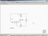
I think Mikes circuit will work for you and you can get the parts at Radio Shack. I think the only FET they have is theIRF510 so you might want to move the top of the switch to the top (+) of the battery.
I think Mikes circuit will work for you and you can get the parts at Radio Shack. I think the only FET they have is theIRF510 so you might want to move the top of the switch to the top (+) of the battery.
If the feed for the switch bypasses the 100 Ohm resistor, then put another small resistor 10 to 100 Ohms in series with the switch. This is to limit the initial charging current for the capacitor to protect the switch's contacts. Could be that the battery's internal impedance is sufficient.
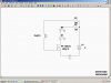
still simpler to use a single schmidt trigger for the timing element. a 3AA holder will fit easily and you could probably get a 3C holder in there! with Cs you could drive 4 whites at 20mA each for 100Hrs
yes and no... move the resistor to the top side of the circuit. where it is it robs the FET of gate voltage reducing the voltage available to the LEDs by a bit more than the gate cut off voltage.
and add a zener to protect the gate from static if it does not already have one built in.
No, he difinitely hasn't out grown it yet. I am just so thankful for everyones input and effort. You guys have spent a lot of your time to help me and have such giving hearts. May God bless you all.
This site uses cookies to help personalise content, tailor your experience and to keep you logged in if you register.
By continuing to use this site, you are consenting to our use of cookies.


")