roadrunnerjohn
New Member
Hello,
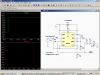
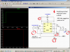
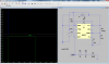
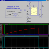
I am building a toy wooden truck and would like to build a circuit that would allow my child to press a button and have headlights (LED's) turn on, and then turn off automatically after about 30 seconds. I can't even seem to work out what type of circuit this is called. If someone knows of one or could design one for me I would really appreciate it.
Thanks so much,
John