Continue to Site

Welcome to our site!

Electro Tech is an online community (with over 170,000 members) who enjoy talking about and building electronic circuits, projects and gadgets. To participate you need to register. Registration is free. Click here to register now.

  • Welcome to our site! Electro Tech is an online community (with over 170,000 members) who enjoy talking about and building electronic circuits, projects and gadgets. To participate you need to register. Registration is free. Click here to register now.

Time delay for 12V motor using 555 IC

Status
Not open for further replies.
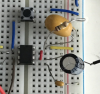
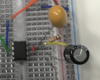
The 10 nano Tantalum, (0.01 uF) - lead is in the positive rails connection point and the Tantalum + lead is at pin 2 of the 555 timer. The pellet can fuse into a short when the part is powered with reverse polarity. If the pellet is fused internally that can make the trigger function act un predictable when operating in connection with the timer.

Sorry if my picture werent clear before. It was actually in the negative rail. The negative lead in the negative rail and the positive lead was beside the wire connecting to Pin 2.
 

Attachments

  • IMG_2280[1].JPG
    IMG_2280[1].JPG
    1.1 MB · Views: 221
A 105 is a 1uF value, for an logic input that's quite a load to alter for the trigger alone, or even for a pull up resistor of the 10k range. That 1 uF KEMET looking part Tantalum part will cause variouse issues on pin 2.
 
A 105 is a 1uF value, for an logic input that's quite a load to alter for the trigger alone, or even for a pull up resistor of the 10k range. That 1 uF KEMET looking part Tantalum part will cause variouse issues on pin 2.


Oh im not sure about that but based on another person that replied to my chat too. i was told to put that capacitor there.
If thats the case would u mind helping me? How should i then connect my circuit in order to allow me to have a timeout of around 26secs and also whenever i On/Off my switch the motor will also start/stop, whether or not the time out of 26secs have been completed.

If i am able to get the above done, i was also looking into how should i allow the time delay to stay consistent in every startup . For eg, if i stopped it after 10secs for the first run, and when i start the next run i will still be able to get 26secs if this time i leave it on all the way till it automatically stops.
 
GromTag, you're about to be sucked down a black hole. Do yourself a favor and read this thread from the beginning, especially the OP's stated (over many posts) triggering and output needs.
If i am able to get the above done, i was also looking into how should i allow the time delay to stay consistent in every startup . For eg, if i stopped it after 10secs for the first run, and when i start the next run i will still be able to get 26secs if this time i leave it on all the way till it automatically stops.
And here, once again, re-stated.

This is the OP's current circuit, as per his stated needs. Component values are as per what we can see in his pictures and what he states.
upload_2017-7-26_9-12-15.png


As you can see, it is a self-triggering monostable timer. The OP has had many inexplicable problems that seem to never end...
 
I did and then I scratched up a circuit sitting right here in front of me on a proto board. press the "momentary" button (tactile) not latching type (miss comprehensions), the timer starts and runs the time set by the resistor and the capacitor, however, press and start again then press the same switch again to cancel the timer resetting for another go using a single switch also. Tho my parts count are a few more than that schematic of yours and yours has less power consumption when the switch is off, thus I'll head elsewhere then.
 
The circuit as drawn, by cowboybob, will always be a retriggerable monostable flip flop. I used a similar circuit. different chips, with a lightning detector to produce one alarm (edit) not matter how many lightnight strikes were detected. So if the alarm was active for 10 minutes, it meant there were numerous lightning strikes from the first to about 8 minutes ago. (end edit)

I've used one exactly like Bob's to extend the time an attenuator was active to reduce cross rate interference. The interval was 8900 uS and I extended it out to almost 18 mS.

Has the TS read the 555 datasheet or any of the numerous articles on using a 555?

Here is the breadboard circuitry using Pebble. I did not put the values in for the capacitors.

Retriggable-Monostable.png


Sadly, the above picture had an error. Below is the corrected picture.

Retriggable-Monostable.png
 
Last edited:

Attachments

  • upload_2017-7-26_18-7-0.png
    upload_2017-7-26_18-7-0.png
    206.8 KB · Views: 208
  • upload_2017-7-26_18-13-25.png
    upload_2017-7-26_18-13-25.png
    142.7 KB · Views: 203
however if i connected the other side of the motor wire lead to the positive rail instead of the negative rail , the motor is able to run. But the timing does not work , it will only stop if i off the switch.
 

Attachments

  • IMG_2281[1].JPG
    IMG_2281[1].JPG
    1.3 MB · Views: 195
What size is your motor? How much current does it draw when you connect it to the listed power source?

What are the specifications with respect to sinking or sourcing current in the 555?

What test equipment do you own?

DMM?
Oscilloscope?
 
Last edited:
What size is your motor? How much current does it draw when you connect it to the listed power source?

What are the specifications with respect to sinking or sourcing current in the 555?

What test equipment do you own?

DMM?
Oscilloscope?


Im using a 12V DC motor. 1020536 3L 1214 thats is what it is written on the motor.
I believe that it was getting about 0.4- 0.5A?

Sorry what do u mean by "What are the specifications with respect to sinking or sourcing current in the 555?

Im not very sure about the names of it but i have like a Power source machine , multimeter and a Pulse generator kind of machine which shows like graph like readings i believe its called an oscilloscope?

Sorry this is the first time im handling with this type of equipments and projects so im not sure about circuiting , electronic stuffs
 
I think the reason why my circuits keep stopping at such short timing is because of the 555IC getting slightly hot. is there any reason or ways in why my 555IC is like that? i changed the 555 too

Or sometimes if it runs for a longer time the 555IC gets really hot.
 
Last edited:
If your motor draws more than 200mA, then driving it directly from the 555 will overload the 555 and cause it to get hot and/or become damaged.
 
If your motor draws more than 200mA, then driving it directly from the 555 will overload the 555 and cause it to get hot and/or become damaged.


Then what should i do to reduce its current? or any way to help cool the IC down while running?
 
Mind showing me how can i make use of a Transistor to reduce its current? like how do i connect my motor/IC and transistor on the Breadboard . Thank you!
 
Here's one way you could do it :
TransistorDriver.PNG

I have not shown all the connections to the 555; just how the output pin 3 drives a transistor.
The transistor can be, for example, a TIP120 or TIP121
The resistor value can be in the 1k to 5k range.
The diode can be, for example, a 1N400x, where x is in the range 1 to 7.
The motor connects to the collector (column 16) and the +ve rail (Y2).

N.B. This layout is shown for simplicity but is not ideal, because motor current is passing through the breadboard connectors (which are intended for low currents only).
 
Status
Not open for further replies.

Latest threads

New Articles From Microcontroller Tips

Back
Top