Continue to Site

Welcome to our site!

Electro Tech is an online community (with over 170,000 members) who enjoy talking about and building electronic circuits, projects and gadgets. To participate you need to register. Registration is free. Click here to register now.

  • Welcome to our site! Electro Tech is an online community (with over 170,000 members) who enjoy talking about and building electronic circuits, projects and gadgets. To participate you need to register. Registration is free. Click here to register now.

Thinking about starting a project...

Status
Not open for further replies.
I'm still trying to get my head around the fact of do you need a joystick or a switch...???
" it need to appear in windows as a joystick."

So you can use an Arduino program that emulates a joystick, but instead of a varying analog value from a pot and ADC (a literal joystick), use the approriate fixed number proportion for whatever notch / switch position is relevant, from the values provided in that list.

Think of it as Windows continually asking the joystick driver "What position is the stick now" - it does not know the source of the replies, or how many possibilities there are, as long as it gets a valid answer.
 
The arduino will just provide "digital signals" The PC and game will decipher these in game..

The notch for example can be mapped to the 'A' key etc..

I was hoping I could get more information on game data extraction, but its above my remit..

JimB Do you have the data on that switch you used, I now have an Arduino micro with said program on it, I could now simulate the output.
ntypeman Do you have the "Train Sim" on Steam... It may be possible to "Gift" it to me...

I'm ready to proceed.... The one thing left are these "solenoids"... What are they for?... If they disable functions, it'll be possible to disable certain functions by transistor.
 
Ian...

please check your PM's... I've sent you a code...

Regarding the soleniods... There are 2 to perform an interlock on the power handle & reverser...

Both solenoids will be "at rest" thus locking each handle... When you insert & turn the master key (ignition key for the want of a better word) it will partially energise the circuit to release the reverser solenoid, but will not energise the circuit until the reverser release button is depressed... Once the button is depressed it completed the circuit, energises the solenoid and the reverser can then be moved to forward or reverse...

When the reverser is in the forward or reverse positions then the solenoid on the power handle will release so it can be moved... If the reverser is in the off position then the power handle should be locked in position...

That's how it should work in theory anyway... there's a few things I'm not too sure about but it's nothing really to worry about at this stage...

Eric
 
Last edited:
So what has JimB been doing?

Here is my prototype modified switch:

Switch General View.JPG


Switch Contacts.JPG


Switch Contacts Annotated.jpg


The self centre-ing action of the HOLD position could maybe do with some improvement, but whether that could be done on a simple mechanism like this I am not sure.

JimB
 
I'd guess it's some form of detent / "plunger" system but I can't say for sure... On the real thing theres a lot goes of "gubbins" under the desk...

Screenshot_20210912-091025_eBay.jpg


I'm not saying that this is what the power handle controls under the desk where you can't see, but what I think is (or more than likely) is under the desk...

Eric
 
I was going to ask the OP to plug a force feedback joystick into the sim to see if it rumbles with speed!! Otherwise it has to be totally notch simulated..
Ian...

Plugged an xbox controller in and can confirm that it does vibrate... Not lots or constantly, just a little now & then...

Eric
 
On the real thing theres a lot goes of "gubbins" under the desk...
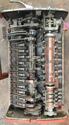
That's in principle a big "Cam switch".

It looks like the largest section at the bottom is the main "notch" section, the grey cam at the top of that has multiple small notches with the lowest roller running in them.

I'd guess the middle section is the on/off switch, with an interlock to the rear segment cam on the notch plate so it cannot release with the main one in a driving notch.

And the the top small section may be the retaining detents for "off" and run up / run down, as the recesses are much deeper than in the main notch plate.

It's similar principles to the older direct controllers I've worked on, but with smaller contacts to switch external control gear rather than the full motor current; eg. this has speed notches on the left & forward/reverse on the right. The "notch" cam & spring roller setup is just under the top plate.

IMG_8532.JPG
 
Ian, JimB, Rj & anyone else who may be interested...

I've been in contact with Chris, who is the developer of the said programme... I've sent him a link to this forum so maybe he will be so gracious & grace us with his presence on this thread... His input could be most helpful...

Eric
 
Hi Everyone, my name is Chris (CobraOne) and I am the author of the 'TS2017 Raildriver and Joystick Interface' that Eric refers to.
The software can be a little overwhelming to start with but it does allow you to create your own controllers and instruments to talk to TS2021.

With regards this project, Eric has two options that I see to connect his switch to a Arduino.
1. Connecting resistors between each contact will in effect turn it into a joystick.
Option 1 (Resistors).jpg


2. Connect each contact to a pin on the Arduino and
(A). Program the Arduino to send the necessary joystick position or
(B). Program the Arduino to send the keyboard commands A and D. This will negate the requirment to use of my program to talk to TS2021.

Option 2 (Single Pins).jpg


If you also wish to display data from TS regarding speed, brake pressure etc then you will need to use my program. You can display the data using LCD's, 7 segment displays or use servo's or stepper motors to create your own analogue gauges.

I am not a professional programmer or an expert on the Arduino but I believe I know enough to help anyone who wishes to use my software to create a train cab.

Chris
 
Status
Not open for further replies.

Latest threads

New Articles From Microcontroller Tips

Back
Top