Continue to Site

Welcome to our site!

Electro Tech is an online community (with over 170,000 members) who enjoy talking about and building electronic circuits, projects and gadgets. To participate you need to register. Registration is free. Click here to register now.

  • Welcome to our site! Electro Tech is an online community (with over 170,000 members) who enjoy talking about and building electronic circuits, projects and gadgets. To participate you need to register. Registration is free. Click here to register now.

Thinking about starting a project...

Status
Not open for further replies.

ntypeman

Member
Hi all,

I have a little / very basic electronics knowledge & this is my first post so please go easy on me!!! :)

For a while now I have contemplated trying to build a custom game controller... i am heavily into train simulators & would ideally like a locomotive power controller to add to the realism. Doesn't have to be a perfect replica of the real thing at this point but as long as it works like the real thing...

The controller has 6 positions, being:

OFF
Run Down
Notch Down
HOLD
Notch Up
Run Up

Let me explain the positions...

OFF (Obviously)
Run Down (automatically decreases the tap changer setting)
Notch Down (manually decreases the tap changer setting)
HOLD (Holds the tap changer at its current setting)
Notch Up (manually increases the tap changer setting)
Run Up (automatically increases the tap changer setting)

Does anyone know of a rotary style switch that has 6 positions, has fixed positions and sprung (or momentary) positions???

The positions OFF, Run Up, HOLD & Run Down are fixed. The positions Notch Up / Notch Down are sprung and when selected will return to the HOLD position...

Or, does anyone know of a way of creating such a switch??? Dunno if I've made any sense but hopefully someone may know what I'm on about...!!!

Thanks in advance

Eric
 
Welcome to ETO.

I understand your problem, I think.
It sounds more of a mechanical problem rather than electrical/electronic.

My first thoughts are that the switching functions could be done by modifying the detents of a six position rotary switch.
(The detents are what hold the switch in place as it is clicked from position to position).

Let me think about this a bit more, its tea time!

JimB
Thanks Jim...

any help is much appreciated...

Eric
 
It could be done using a built-up detent system, so a hidden arm with a sprung roller and a "sawtooth" style detent with some teeth replaced by ramps, to give spring return if the handle was not moved all the way to the next notch.

The electrical switch could be a wafer style with no detent, or have a magnet on the arm operating magnetic reed switches as it moved.

However, I'm a bit puzzled - you say you want a realistic style controller, but as far as I know, no normal locomotives have a system such as you describe?
 
I have an old joystick... I wanted to use said joystick on my raspberry pi..

So... I got hold of an Arduino micro ( with 32u4 chip on ) .. I mounted the micro to a piece of stripboard and soldered a 9 pin d socket at the end..

I got them both on fleabay.. less than a fiver! Thing is... The source code is openware so I can now do pretty much what I like.. I could do what you wanted with a "normal" 6 way switch and use software to trick the system..

Now!! The big thing is windows / linux etc.. They expect buttons and analogue switches.. However!! they do allow an awfull amount of buttons on a game controller so buttons arranged in a circle would also do...

Just saying...
 
It could be done using a built-up detent system, so a hidden arm with a sprung roller and a "sawtooth" style detent with some teeth replaced by ramps, to give spring return if the handle was not moved all the way to the next notch.

The electrical switch could be a wafer style with no detent, or have a magnet on the arm operating magnetic reed switches as it moved.

However, I'm a bit puzzled - you say you want a realistic style controller, but as far as I know, no normal locomotives have a system such as you describe?
Hi rjenkinsgb...

thanks for taking the time to reply... In answer to your question the locomotives in question are British Rail classes 81 - 87, all sadly since withdrawn now :(

They all used a tap changer control system hence my question in wanting to recreate a suitable controller...

Without wishing to bore you, if you want to see what I'm on about then take a look at this link:


The power handle is the large curved handle which the driver is manually manipulating the tap changer whilst pulling away...

Eric
 
Last edited:
I got them both on fleabay.. less than a fiver! Thing is... The source code is openware so I can now do pretty much what I like.. I could do what you wanted with a "normal" 6 way switch and use software to trick the system..
Ian...

Sounds interesting... the game i play is Train Simulator 2021 (soon to be 2022, that aside) it's a windows based system... Some people have commercially created controls using arduino boards but the said companies want money I just don't have :( hence me wanting to try & recreate myself on a budget...!!!

Arduino boards have also been mentioned on the Train Simulator forum I frequent but I have absolutely NO idea what you have to do with them...!!!

Eric
 
OK, I was thinking it was for a generic controller rather than for a specific type of locomotive; that's a system I'd never seen, though it sounds a bit like it could be a descendant of the VAMBAC system used on some trams - I've repaired one of those.

Back to the real subject:
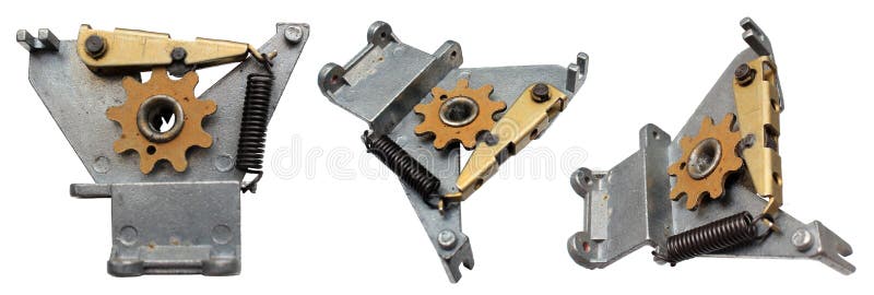
I cannot find any pictures much like the mechanism I was thinking of; this is the nearest:

Imagine the "teeth" spread out on a larger diameter quadrant, then for the spring return positions replace the tooth between those two notches with a ramp, so the spring roller lifts as you move to the momentary position and runs back down, returning the lever, when it is released.

The arc part could be metal wood, or 3D printed, with a small ballrace & spring mechanism for the roller part.

Set the teeth at the correct angles and you could add a switch wafer to the spindle that turns the quadrant, or use individual microswitches or slotted optical switches arranged around it.
 
then for the spring return positions replace the tooth between those two notches with a ramp, so the spring roller lifts as you move to the momentary position and runs back down, returning the lever, when it is released.
That is exactly what I had in mind.
Not only that, I have found some switches which are suitable for modification.
If I can get enough enthusiasm in the next ??? I will give it a go and modify one.

JimB
 
Looking at that video, the controller appears to be two detents each way but entirely sprung to centre; no latch away from that?
 
That is exactly what I had in mind.
Not only that, I have found some switches which are suitable for modification.
If I can get enough enthusiasm in the next ??? I will give it a go and modify one.

JimB
Jim...

Getting excited now!!!

Eric
 
This is a view of the power controller, the smaller lever to the left is the "reverser" (Forward, OFF, Reverse)

Screenshot_20210821-225440_Google.jpg
 
Is it an optical illusion that the main (big) lever in this image appears to be rotary, but the one in the video appears to be linear (back and forth)?

Also, the embossed graphic in the image above appears to show two clicks between Hold and the extreme clockwise detent position; and two clicks, but no detent in the extreme anticlockwise position?
 
the locomotives in question are British Rail classes 81 - 87
My detailed knowledge of locomotive types ran out in the mid '60s with 9Fs and Deltics!

Getting excited now!!!
Well, I have just had a happy hour on the tools in my mechanical workshop (aka garage), and I have modified a switch mechanism in the manner proposed above.

The good news is that it works in principle, but could stand a bit more fettling, maybe on another mechanism, to make it work a bit more like the real thing.

Look at the pictures...

The switch mechanism:
Switch Mechanism.JPG

I left the spring off because it is a tough mean finger busting little thing.

To give you an idea of the scale of this thing, the shaft through the switch is 62mm overall length.

The individual components:
Switch Components.JPG


And the end view of the modified detents on the shaft:
Detents Modified.JPG


The problem with this is that where I have filed away the detents, in order to get sufficient angle for the little roller which engages with the detents to slide into the HOLD position, I have removed a bit too much metal such that the spring is practically closed up and providing very little force to hold the switch in position.

But hey ho, there has to be several ways to sort that.

JimB
 
Ian...

Sounds interesting... the game i play is Train Simulator 2021 (soon to be 2022, that aside) it's a windows based system... Some people have commercially created controls using arduino boards but the said companies want money I just don't have :( hence me wanting to try & recreate myself on a budget...!!!

Arduino boards have also been mentioned on the Train Simulator forum I frequent but I have absolutely NO idea what you have to do with them...!!!

Eric
Kinda nothing.... The code is written.. The board is made... The IDE and compiler is free... You can get a micro for £3 ish... just need a few buttons and a USB lead ( that comes with the micro sometimes )

I have a crane simulator ... But as a crane control is similar to a XBOX ( two levers and a ton of buttons ) I got one at ADSA for £20..

Does all I need..

As for the code... They have kindly commented it so slight adjustments are easy... Ultimately it's up to you... My Pi conversion works like a dream..
I have PiMiga and the old competition pro is still the best joystick for the amiga..
 
My detailed knowledge of locomotive types ran out in the mid '60s with 9Fs and Deltics!


Well, I have just had a happy hour on the tools in my mechanical workshop (aka garage), and I have modified a switch mechanism in the manner proposed above.

The good news is that it works in principle, but could stand a bit more fettling, maybe on another mechanism, to make it work a bit more like the real thing.

Look at the pictures...

The switch mechanism:
View attachment 133282
I left the spring off because it is a tough mean finger busting little thing.

To give you an idea of the scale of this thing, the shaft through the switch is 62mm overall length.

The individual components:
View attachment 133283

And the end view of the modified detents on the shaft:
View attachment 133284

The problem with this is that where I have filed away the detents, in order to get sufficient angle for the little roller which engages with the detents to slide into the HOLD position, I have removed a bit too much metal such that the spring is practically closed up and providing very little force to hold the switch in position.

But hey ho, there has to be several ways to sort that.

JimB
Jim...

I'm gobsmacked... You did that in an hour???!!!

Maybe, just maybe this project may get off the ground with the help of you bunch of amazing people...!!!

One thing I omitted to say (sorry!!! :confused:) is that the lever quadrant turns through 90° - 120°... I think in reality it's 90° but I'd accept up to 120° if it makes things easier to make...

Can't thank you enough for your helpful input... :)

Eric
 
Is it an optical illusion that the main (big) lever in this image appears to be rotary, but the one in the video appears to be linear (back and forth)?
Hi Buk...

Yes its an optical illusion, it's a rotary switch that moves through (I think 90°) but when the driver operates the power controller, it looks as if he's just moving it backwards and forwards...

Also, the embossed graphic in the image above appears to show two clicks between Hold and the extreme clockwise detent position; and two clicks, but no detent in
Little bit confused about what you are asking about this??? I'll explain how the controller works if it make it easier for you???

Starting in OFF the handle is moved to the HOLD position then to the NOTCH UP position and released so it springs back to the HOLD position... As the speed increases & the ammeter decreases, the driver manipulates this process until such time that the handle can be mover to the RUN UP position to let the tap changer do it's stuff without overloading the ammeter (traction motors)

Once the tap changer has reached it's maximum of 38 notches (I think off the top of my head), the handle can now be moved back to the HOLD position until such time that the driver either:

1. Returns the handle back to the OFF position (in which case the tap changer automatically runs down from notch 38 (or what ever notch it's in) to notch 0, BUT, during this time power CAN NOT be reapplied UNTIL the tap changer has reached notch 0...)...

2. Returns the handle to the RUN DOWN position in which case the tap changer will automatically decrease the notches until the driver chooses to move the handle to HOLD or NOTCH DOWN / NOTCH UP /RUN UP positions

3. Moves the handle to the NOTCH DOWN position and then releases the handle which then springs back to the HOLD position. This must be repeated if the driver want to make fine adjustments to the tap changer...

Apologies about the essay, has it made anything clearer for you??? The YouTube video I posted further up in the post may make things a bit clearer if you watch it...

Eric
 
One thing I omitted to say (sorry!!! :confused:) is that the lever quadrant turns through 90° - 120°... I think in reality it's 90° but I'd accept up to 120° if it makes things easier to make...
Most off the shelf rotary switches have 30 degrees between steps, your controller has six positions, ie five steps, so modifying a standard rotary switch as I have done will result in a total control lever travel of 150 degrees.

To produce a controller with a 90 degree overall movement would be a large task, probably involving making everything from scratch.

JimB
 
Status
Not open for further replies.

Latest threads

New Articles From Microcontroller Tips

Back
Top