Hello everybody. Hopefully someone could help me with my topic.
I'm creating a dynamical thermal model of an IGBT power module from ABB:
https://www05.abb.com/global/scot/scot256.nsf/veritydisplay/70bb90c34ed25dcbc1256ff50050ef85/$file/5SNA%201200E330100_5SYA1556-03May%2005.pdf
This module is mounted onto a heat sink with water cooling. Therefore the complete system contains the IGBT module and the heat sink. Also the power module consists of an IGBT and a freewheeling diode (FWD) inside. Thus the final model must comprise the IGBT, the FWD and the heat sink.
The thermal model for the IGBT and FWD could be easily derived with the aid of datasheet parameters and equivalent RC-network (called Foster network) as depicted at Fig.A:

The values of capacitors and resistors are derived from the datasheet mentioned above, using the thermal impedance Zth_jc data. The terms pt(t) and pd(t) represent the instantaneous power losses in the IGBT and FWD respectively. These signals are known. Tjt and Tjd are the junction temperature of IGBT and FWD. Tc is the power module case temperature.
The case of Fig.A is well described in the literature (Seimikron Application Book, e.g.) and because of this I am pretty sure of it.
The problems start, when I'm trying to include the dynamical thermal model for the heat sink to the system. Information about this model is poor (datasheet infos are not enough, an exact description in the literature wasn't found). Thus I have done the model by myself according to the physical representaion (Cauer network) as depicted at Fig.B:
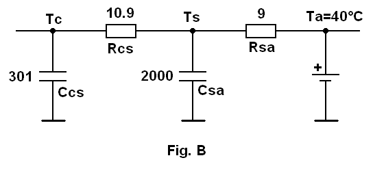
Tc - power module case temperature (the same as at Fig.A);
Ts - temperature of the heat sink;
Ta - temperature of the cooling water, which is assumed as a constant of 40 °C (modelled by a DC-source);
Ccs - thermal capacity of the power module base plate (thermal capacity of the thermal grease is neglected);
Csa - thermal capacity of the heat sink;
Rcs - thermal resistance of used thermal grease (according to its datasheet);
Rsa - thermal resistance of the heat sink provided by the manufacturer.
From this point some questions appear:
1) The MAIN QUESTION: how could the circuits at Fig.A and Fig.B be combined??? According to the literature (Semikron App.Book) it cannot be done just by connecting the circuits directly in the Tc point!
2) The thermal capacity of the base plate seems not to be included in the thermal impedance Zth_jc in the IGBT module datasheet. That's why I added it to the circuit at Fig.B as Ccs. Is it right?
3) Calculation of the thermal capacitances Ccs and Csa? I used the formula:
C = m•c, where m - mass of the material in "kg", c - specific heat of the material in "J/(kg•K)"
Is it right?
4) Is the model at Fig.B correct at all? Did I forget something?
I would be grateful for any help!
I'm creating a dynamical thermal model of an IGBT power module from ABB:
https://www05.abb.com/global/scot/scot256.nsf/veritydisplay/70bb90c34ed25dcbc1256ff50050ef85/$file/5SNA%201200E330100_5SYA1556-03May%2005.pdf
This module is mounted onto a heat sink with water cooling. Therefore the complete system contains the IGBT module and the heat sink. Also the power module consists of an IGBT and a freewheeling diode (FWD) inside. Thus the final model must comprise the IGBT, the FWD and the heat sink.
The thermal model for the IGBT and FWD could be easily derived with the aid of datasheet parameters and equivalent RC-network (called Foster network) as depicted at Fig.A:
The values of capacitors and resistors are derived from the datasheet mentioned above, using the thermal impedance Zth_jc data. The terms pt(t) and pd(t) represent the instantaneous power losses in the IGBT and FWD respectively. These signals are known. Tjt and Tjd are the junction temperature of IGBT and FWD. Tc is the power module case temperature.
The case of Fig.A is well described in the literature (Seimikron Application Book, e.g.) and because of this I am pretty sure of it.
The problems start, when I'm trying to include the dynamical thermal model for the heat sink to the system. Information about this model is poor (datasheet infos are not enough, an exact description in the literature wasn't found). Thus I have done the model by myself according to the physical representaion (Cauer network) as depicted at Fig.B:
Tc - power module case temperature (the same as at Fig.A);
Ts - temperature of the heat sink;
Ta - temperature of the cooling water, which is assumed as a constant of 40 °C (modelled by a DC-source);
Ccs - thermal capacity of the power module base plate (thermal capacity of the thermal grease is neglected);
Csa - thermal capacity of the heat sink;
Rcs - thermal resistance of used thermal grease (according to its datasheet);
Rsa - thermal resistance of the heat sink provided by the manufacturer.
From this point some questions appear:
1) The MAIN QUESTION: how could the circuits at Fig.A and Fig.B be combined??? According to the literature (Semikron App.Book) it cannot be done just by connecting the circuits directly in the Tc point!
2) The thermal capacity of the base plate seems not to be included in the thermal impedance Zth_jc in the IGBT module datasheet. That's why I added it to the circuit at Fig.B as Ccs. Is it right?
3) Calculation of the thermal capacitances Ccs and Csa? I used the formula:
C = m•c, where m - mass of the material in "kg", c - specific heat of the material in "J/(kg•K)"
Is it right?
4) Is the model at Fig.B correct at all? Did I forget something?
I would be grateful for any help!
") And I'm not sure, that the FEM approach is really required here. Because if we consider the heat being spread only in one dimension (directly from case through thermal grease and heatsink to the ambient) and that the heat sink is homogeneously heated (its temperature is the same throughout the whole volume), than we can still use one RC-network for each "layer" as done at Fig.B. It would have some discrepancy from reality, but as already said, I want to avoid the FEM as long as possible.
And I'm not sure, that the FEM approach is really required here. Because if we consider the heat being spread only in one dimension (directly from case through thermal grease and heatsink to the ambient) and that the heat sink is homogeneously heated (its temperature is the same throughout the whole volume), than we can still use one RC-network for each "layer" as done at Fig.B. It would have some discrepancy from reality, but as already said, I want to avoid the FEM as long as possible.