Electro Tech is an online community (with over 170,000 members) who enjoy talking about and building electronic circuits, projects and gadgets. To participate you need to register. Registration is free. Click here to register now.
Welcome to our site! Electro Tech is an online community (with over 170,000 members) who enjoy talking about and building electronic circuits, projects and gadgets. To participate you need to register. Registration is free. Click here to register now.
A 2N3055 is in a TO-3 metal case and can dissipate a max of 115W of heat if its heatsink is perfect.
A TIP3055 is in a TO-218 plastic case with a metal tab and can dissipate a max of only 90W of heat if its heatsink is perfect.
If the inverter is designed to use 2N3055 transistors then the heatsink or fan must be bigger if TIP3055 transistors are used.
You might need to add more transistors to divide the heat.
That project doesn't work anymore.
I corrected it years ago but recently it was changed by MP.
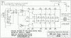
Now it might give an output of only 250W if its output transistors are matched and if its oscillator is fixed. It uses two quad opamps instead of one dual opamp.
Here is my version that people said has an output of up to 720W:
Thanks for that. Here is another problem: Am I going to direct all the GND in the circuit to one point( This is my first project). Secondly, the -ve terminal of the battery, where will it go to. Thank you.
This inverter has a square-wave output. Some electronic products won't work properly when powered by it.
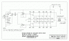
Use two heatsinks, one for each side. Then the transistors can be bolted to the heatsinks with thermal grease but no insulators, then insulate the heatsinks from each other and from the grounded metal case. Then the cooling will be best.
Mount the 0.1 ohm emitter resistors on the heatsinks soldered to each emitter and to a terminal strip. Connect the terminal strip to ground (- of the battery) with a very thick wire and connect it to the ground of the circuit board with a thin wire.
Bolt a terminal to each heatsink and connect them to the transformer with thick wire.
Connect together the 50A fuse and switch with thick wire.
Connect the + of the battery to the fuse with thick wire.
Connect the switch to the transformer with thick wire and connect the switch to the circuit board with thin wire.
Connect the output of the opamps to the bases of the pre-driver transistors with thin wires.
Where are you going to get the huge and expensive transformer?
This inverter has a square-wave output. Some electronic products won't work properly when powered by it.
Use two heatsinks, one for each side. Then the transistors can be bolted to the heatsinks with thermal grease but no insulators, then insulate the heatsinks from each other and from the grounded metal case. Then the cooling will be best.
Mount the 0.1 ohm emitter resistors on the heatsinks soldered to each emitter and to a terminal strip. Connect the terminal strip to ground (- of the battery) with a very thick wire and connect it to the ground of the circuit board with a thin wire.
Bolt a terminal to each heatsink and connect them to the transformer with thick wire.
Connect together the 50A fuse and switch with thick wire.
Connect the + of the battery to the fuse with thick wire.
Connect the switch to the transformer with thick wire and connect the switch to the circuit board with thin wire.
Connect the output of the opamps to the bases of the pre-driver transistors with thin wires.
Where are you going to get the huge and expensive transformer?
Thank you so much, I will get in touch as the the project proceeds. Thank you once again. As for where I will get the big transformer, I have one and I think I can make one also.
That project doesn't work anymore.
I corrected it years ago but recently it was changed by MP.
Now it might give an output of only 250W if its output transistors are matched and if its oscillator is fixed. It uses two quad opamps instead of one dual opamp.
Here is my version that people said has an output of up to 720W:
Well the output is just a square wave square wave is made up of odd numbered harmonics ie 50 hz square wave = 50hz,150 hz, 250 hz,350hz and so on) .. Well some equipment does not handle these extra harmonics well usually inductive items like motors(fridges, washing machines(older type) as the higher frequency can cause higher voltage/currents to burn the them out. Most modern gear which converts the AC to DC for use in flyback circuits will not be affected (ie new tv, computers)
An electronic product with a linear power supply charges its main filter capacitor to the peak of the sine-wave voltage from the transformer (minus the rectifier's voltage drop).
So if the mains is 230VAC and the transformer in the product reduces it to 20VAC then its peak voltage is 28.3VDC.
A square-wave inverter has an average output voltage of 230VAC and its peak is also 230VAC. Then the transformer in the product reduces it to 20VAC and the peak voltage is only 20VDC.
The product probably works poorly or doesn't work with its DC voltage so low.
Heaters and incandescent lights work fine.
Multi-voltage TVs work fine.
Power tools with variable-speed electric motors work poorly from a square-wave inverter.
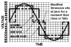
So modified sine-wave inverters are used instead. They have a peak voltage that is higher than the average voltage:
Thanks for that information. Does the diesel powered generator also produce a square wave? Secondly, can I get a sine wave inverter schematic? Thank you.
An electronic product with a linear power supply charges its main filter capacitor to the peak of the sine-wave voltage from the transformer (minus the rectifier's voltage drop).
So if the mains is 230VAC and the transformer in the product reduces it to 20VAC then its peak voltage is 28.3VDC.
A square-wave inverter has an average output voltage of 230VAC and its peak is also 230VAC. Then the transformer in the product reduces it to 20VAC and the peak voltage is only 20VDC.
The product probably works poorly or doesn't work with its DC voltage so low.
Heaters and incandescent lights work fine.
Multi-voltage TVs work fine.
Power tools with variable-speed electric motors work poorly from a square-wave inverter.
So modified sine-wave inverters are used instead. They have a peak voltage that is higher than the average voltage:
This site uses cookies to help personalise content, tailor your experience and to keep you logged in if you register.
By continuing to use this site, you are consenting to our use of cookies.

 hm:
hm: